eHouse LAN Smart Home – EthernetRoomManager Rev. 2,3,4 connection – DIY
Ethernet eHouse Home Automation controllers EthernetRoomManager , EthernetHeatManager , EthernetSolarManager – connection
Smart Home eHouse – smart house.
Ethernet controllers “Do It Yourself” self installation and connection.
These description refers to the middle-range Ethernet Controllers in Revision 2,3,4 (with green Power and ADC sockets):
- EthernetRoomManager
- EthernetHeatManager
- EthernetSolarManager
- Other dedicated Ethernet drivers based on the same PCB
Description NOT involve large controllers
- CommManager
- LevelManager
Most eHouse controllers connectors are double-row IDC connectors with different numbers of pins , for easy installation and quick connection, and ensuring easy assembly concealed through the use of flat cables with clenched IDC connectors at their ends (with special crimper connector IDC) . Assembly and disassembly wiring does not require chiselling grooves in the walls due to the thickness of the flat strip is about 1mm .
You do not need a screwdriver at all, to connect large number of cables to the controller and tighten the socket flat cable regardless of the number of cores takes several seconds. This facilitates fast and easy removal for diagnostics and maintenance of the controller for the detection of problems with installation.
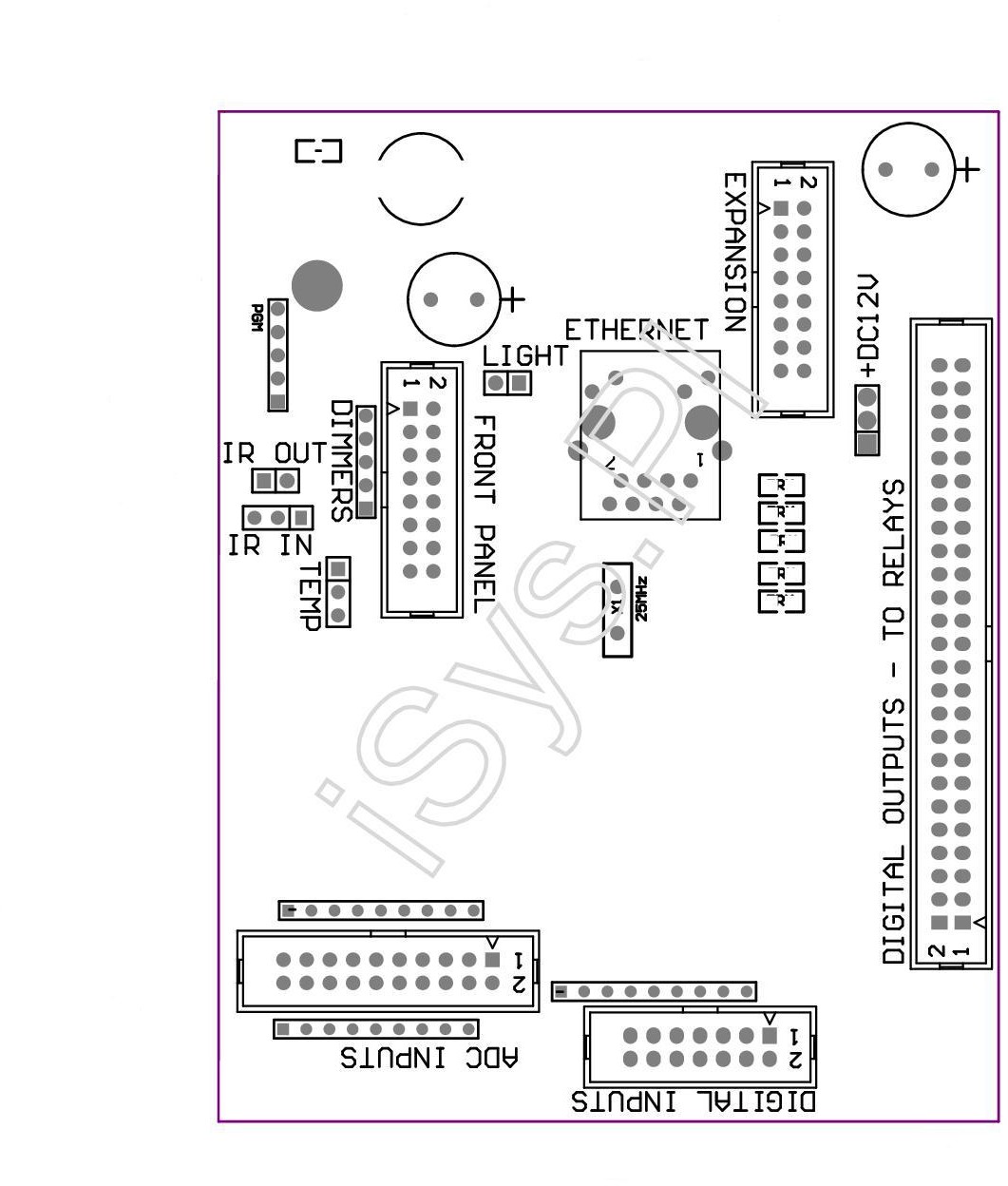
EthernetRoomManager Rev 2.
 Lead of ethernet eHouse Intelligent home EthernetRoomManager , EthernetHeatManager , EthernetSolarManager
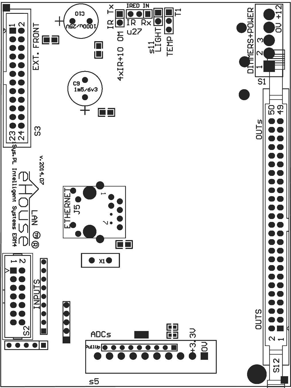
EthernetRoomManager Rev. 3,4
 Lead of ethernet eHouse Intelligent home EthernetRoomManager , EthernetHeatManager , EthernetSolarManager
Pin No. 1 . is marked with a square box solder on the PCB and also an arrow on the housing socket. The first pin is marked with arrow. There is also protection to prevent against reverse insertion of the plug.
The pins are numbered sequentially with priority columns :
____________________________________________________________
| 2 4 6 8 10 12 14 16 18 20 22 24 26 28 30 32 34 36 38 40 42 44..
| 1 3 5 7 9 11 13 15 17 19 21 23 25 27 29 31 33 35 37 39 41 43..
| ^ _______________________ ________________________________
ADC INPUTS – Analog/Digital Converter – Measurement Inputs – (ADC INPUTS ) (0 ; 3 , 3V ) Relative Weights – Do not connect any external voltage (IDC – 20)
Rev < 3
- 1 – Gnd / Ground ( 0V)
- 2 – Gnd / Ground ( 0V)
- 3 – ADC IN 2
- 4 – ADC IN 10
- 5 – ADC IN 3
- 6 – ADC IN 11 / DIGITAL INPUT 12 *
- 7 – ADC IN 4
- 8 – ADC IN 12 / DIGITAL INPUT 11 *
- 9 – ADC IN 5
- 10 – ADC IN 13 / DIGITAL INPUT 10 *
- 11 – ADC IN 6
- 12 – ADC IN 14 / DIGITAL INPUT 9 *
- 13 – ADC IN 7
- 14 – ADC IN 15 / DIGITAL INPUT 8 *
- 15 – ADC IN 8 (optional temperature sensor mounted on the module or panel outside ERM )
- 16 – ADC IN 0
- 17 – ADC IN 9 (optional mounted light sensor ( phototransistor +) or ERM module External Panel )
- 18 – ADC IN 1
- 19 – VDD ( +3,3V ) – Requires a jumper to power the ERM limiting current / temperature sensors for power ( resistor 100 OM )
- 20 – VDD ( +3,3V )
Rev 3+ Single Row 10 pin sockets
- 1 – Gnd / Ground ( 0V) – can be recognized by wide tracks on PCB
- 2 – AVDD ( +3,3V) – can be recognized by wide tracks on PCB
- 3 – ADC IN 2
- 4 – ADC IN 4
- 5 – ADC IN 5
- 6 – ADC IN 6
- 7 – ADC IN 7
- 8 – ADC IN 10
- 9 – ADC IN 0
- 10 – ADC IN 1
DIGITAL INPUTS – Digital Inputs ( On / Off) short to ground or opening ( do not connect any external voltage ) (IDC – 14)
- 1 – Gnd / Ground ( 0V)
- 2 – Gnd / Ground ( 0V)
- 3 – Digital Input / Digital Input 1
- 4 – Digital Input / Digital Input 2
- 5 – Digital Input / Digital Input 3
- 6 – Digital Input / Digital Input 4
- 7 – Digital Input / Digital Input 5
- 8 – Digital Input / Digital Input 6
- 9 – Digital Input / Digital Input 7
- 10 – Digital Input / Digital Input 8 *
- 11 – Digital Input / Digital Input 9 *
- 12 – Digital Input / Digital Input 10 *
- 13 – Digital Input / Digital Input 11 *
- 14 – Digital Input / Digital Input 12 *
* Shorten with rest of analog inputs
DIGITAL OUTPUTS (Rev < 5) – Digital outputs with drivers relays for direct connection of a control relay coil (IDC – 40 or IDC – 50 )
- 1 – VCCDRV – protection against – overvoltage relay connected to a 12V relay coil ( diode to VCC )
- 2 – VCCDRV – protection against – overvoltage relay connected to a 12V relay coil ( diode to VCC )
- 3 – Digital output for direct connection to the relay coil (12V / 20mA ) No . 1
- 4 – Digital output for direct connection to the relay coil (12V / 20mA ) No . 2
- 5 – Digital output for direct connection to the relay coil (12V / 20mA ) No . 3
- 6 – Digital output for direct connection to the relay coil (12V / 20mA ) No . 4
- 7 – Digital output for direct connection to the relay coil (12V / 20mA ) No . 5
- 8 – Digital output for direct connection to the relay coil (12V / 20mA ) No . 6
- 9 – Digital output for direct connection to the relay coil (12V / 20mA ) No . 7
- 10 – Digital output for direct connection to the relay coil (12V / 20mA ) No . 8
- 11 – Digital output for direct connection to the relay coil (12V / 20mA ) No . 9
- 12 – Digital output for direct connection to the relay coil (12V / 20mA ) No . 10
- 13 – Digital output for direct connection to the relay coil (12V / 20mA ) No . 11
- 14 – Digital output for direct connection to the relay coil (12V / 20mA ) No . 12
- 15 – Digital output for direct connection to the relay coil (12V / 20mA ) No . 13
- 16 – Digital output for direct connection to the relay coil (12V / 20mA ) No . 14
- 17 – Digital output for direct connection to the relay coil (12V / 20mA ) No . 15
- 18 – Digital output for direct connection to the relay coil (12V / 20mA ) No . 16
- 19 – Digital output for direct connection to the relay coil (12V / 20mA ) No . 17
- 20 – Digital output for direct connection to the relay coil (12V / 20mA ) No . 18
- 21 – Digital output for direct connection to the relay coil (12V / 20mA ) No . 19
- 22 – Digital output for direct connection to the relay coil (12V / 20mA ) No . 20
- 23 – Digital output for direct connection to the relay coil (12V / 20mA ) No . 21
- 24 – Digital output for direct connection to the relay coil (12V / 20mA ) No . 22
- 25 – Digital output for direct connection to the relay coil (12V / 20mA ) No . 23
- 26 – Digital output for direct connection to the relay coil (12V / 20mA ) No . 24
- 27 – Digital output for direct connection to the relay coil (12V / 20mA ) No . 25
- 28 – Digital output for direct connection to the relay coil (12V / 20mA ) No . 26
- 29 – Digital output for direct connection to the relay coil (12V / 20mA ) No . 27
- 30 – Digital output for direct connection to the relay coil (12V / 20mA ) No . 28
- 31 – Digital output for direct connection to the relay coil (12V / 20mA ) No . 29
- 32 – Digital output for direct connection to the relay coil (12V / 20mA ) No . 30
- 33 – Digital output for direct connection to the relay coil (12V / 20mA ) No . 31
- 34 – Digital output for direct connection to the relay coil (12V / 20mA ) No . 32
- 35 – Digital output for direct connection to the relay coil (12V / 20mA ) No . 33
- 36 – Digital output for direct connection to the relay coil (12V / 20mA ) No . 34
- 37 – Digital output for direct connection to the relay coil (12V / 20mA ) No . 35
- 38 – GND / 0V ( supply power via this connector ONLY at that in the case of flat cable length less than 50cm )
- 39 – GND / 0V ( supply power via this connector ONLY at that in the case of flat cable length less than 50cm )
- 40 – GND / 0V ( supply power via this connector ONLY at that in the case of flat cable length less than 50cm )
- 41 – GND / 0V ( supply power via this connector ONLY at that in the case of flat cable length less than 50cm )
- 42 – GND / 0V ( supply power via this connector ONLY at that in the case of flat cable length less than 50cm )
- 43 – GND / 0V ( supply power via this connector ONLY at that in the case of flat cable length less than 50cm )
- 44 – GND / 0V ( supply power via this connector ONLY at that in the case of flat cable length less than 50cm )
- 45 – GND / 0V ( supply power via this connector ONLY at that in the case of flat cable length less than 50cm )
- 46 – GND / 0V ( supply power via this connector ONLY at that in the case of flat cable length less than 50cm )
- 47 – GND / 0V ( supply power via this connector ONLY at that in the case of flat cable length less than 50cm )
- 40 – GND / 0V ( supply power via this connector ONLY at that in the case of flat cable length less than 50cm )
- 49 – + 12V power input ERM ( alternatively with power connector at that in the case of flat cable length less than 100cm )
- 50 – + 12V power input ERM ( alternatively with power connector at that in the case of flat cable length less than 100cm )
POWER DC 12V (3 – Pin connector ) Rev. 1,2
- 1 – GND / Ground / 0V
- 2 – GND / Ground / 0V
- 3 – + 12V / 0.5A ( Power Driver ) UPS – with battery voltage (optional)
Dimmers – output PWM dimmers ( 5 pin Socket – SIP) (Rev. 1,2 – NO Power drivers)
- 1 – PWM 1 ( PWM dimmer output 1 or red TTL – without power driver ) 3 . 3V / 10mA ( for control LED driver optocoupler transmit power – ANODE )
- 2 – PWM 2 (Output 2 PWM dimmer or green TTL – without power driver ) 3 . 3V / 10mA ( for control LED driver optocoupler transmit power – ANODE )
- 3 – PWM 3 ( PWM dimmer output 3 or blue TTL – without power driver ) 3 . 3V / 10mA ( for control LED driver optocoupler transmit power – ANODE )
- 4 – GND / Ground / 0V – The cathodes of diodes optocoupler transmit power drivers *
- 5 – + 12VDC power supply (input / output max 100mA ) *
* Power EthernetRoomManager from Dimmers Power Drivers ( disconnect other power supply ( +12 VDC ) provide a very good common ground especially to Router Ethernet
Power supply + Dimmers – output PWM dimmers with drivers( 5 pin Socket – GREEN) (Rev. 3,4)
- 1 – PWM 1 ( PWM dimmer output 1 or red ) 12VDC / 3A ( for drive LED strips – Cathodes ) (Squared point on PCB)
- 2 – PWM 2 (Output 2 PWM dimmer or green) 12VDC / 3A ( for drive LED strips – Cathodes )
- 3 – PWM 3 ( PWM dimmer output 3 or blue) 12VDC / 3A ( for drive LED strips – Cathodes )
- 4 – GND / Ground / 0V
- 5 – + 12VDC/500mA power supply input
FRONT PANEL – ExternalPanel expansion connector (IDC – 16) – only to connect native eHouse system components (Rev. 1,2,3,4)
- 1 – + 12VDC power supply (input / output max 100mA ) *
- 2 – + 12VDC power supply (input / output max 100mA ) *
- 3 – Digital Output No. 34 (without driver)
- 4 – VCC 3.3V (output internal regulator to power the panel )
- 5 – IR IN ( input from an external IR receiver )
- 6 – ADC IN 8 (optional temperature sensor mounted on the module or panel outside ERM )
- 7 – TX1 (RS232 TTL Transmit ) or other functions for the external panel ( do not connect external devices )
- 8 – RX1 (RS232 TTL Reception ) or other functions for the external panel
- 9 – ADC IN 9 (optional mounted light sensor ( phototransistor +) ERM module or an external panel )
- 10 – PWM 1 ( PWM dimmer output 1 or red TTL – without power driver ) 3 . 3V / 10mA ( for control LED driver optocoupler transmit power)
- 11 – PWM 2 ( PWM dimmer Output 2 or green TTL – without power driver ) 3 . 3V / 10mA ( for control LED driver optocoupler transmit power)
- 12 – PWM 3 ( PWM dimmer output 3 or blue TTL – without power driver ) 3 . 3V / 10mA ( for control LED driver optocoupler transmit power)
- 13 – IR OUT – IR transmitter output (for connecting broadcasting IR LEDs and current limiting resistor 12V / 500mA )
- 14 – RESET – Reset the controller ( active low )
- 15 – GND / Ground / 0V *
- 16 – GND / Ground / 0V *
* To Power EthernetRoomManager from the ExternalPanel ( disconnect other power supply ( +12 VDC ) – provide a very good common ground especially with Ethernet Switch
ETHERNET – RJ45 LAN Jack for LAN ( 10Mbs )
This is a standard Ethernet socket RJ45 connector requiring clamped on the cable UTP-8 .
LIGHT – Light sensor ( 2 pin ) – optional light sensor mounted alternatively on ExternalPanel (Rev. 1,2,3,4)
- 1 – GND / Weight / 0V
- 2 – PHOTOTRANSISTOR + (or other light-sensitive element Photodiode , photoresistor ) ADC IN 9 (optional light sensor mounted on the module or panel outside ERM )
TEMP – Temperature Sensor ( 3 pin ) – optionally , alternatively, a temperature sensor mounted on the ExternalPanel (MCP9701 , MCP9700) (Rev. 1,2,3,4)
- 1 – 3 , 3V power supply temperature sensor
- 2 – ADC IN 8 (optional temperature sensor mounted on the module or panel outside ERM )
- 3 – GND / Ground / 0V
Do not connect external devices, interfaces of different variants eHouse controllers. Connection to other signals may damage controller.
These pins are shorted to pin digital inputs , analog , digital outputs directly on the processor without any security .
Connection diagram of ERM rev. 3,4:
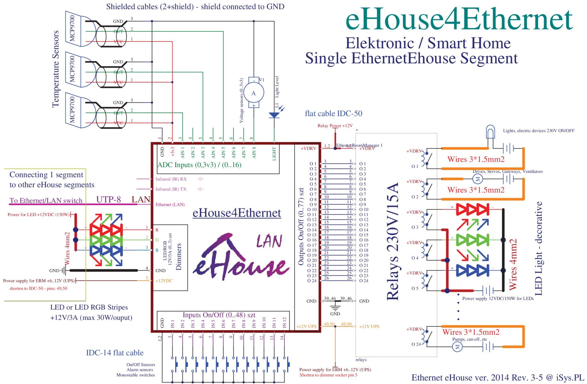 connection of ethernet eHouse Intelligent home EthernetRoomManager , EthernetHeatManager , EthernetSolarManager
connection erm – pdf
More info on ERM:
Smart House eHouse – Ethernet Room Controller