eHouse LAN smart home – CommManager , LevelManager connection
eHouse Ethernet Smart Home controllers
Connecting CommManager, LevelManager and other big eHouse Ethernet controllers
Most eHouse controllers connectors are double-row IDC connectors with different numbers of pins for easy installation and quick connection , and ensuring easy assembly concealed through the use of flat cables with clenched IDC connectors at their ends ( special crimper connector IDC ) . Assembly and disassembly wiring does not require chiselling grooves in the walls due to the thickness of the flat strip is about 1mm . 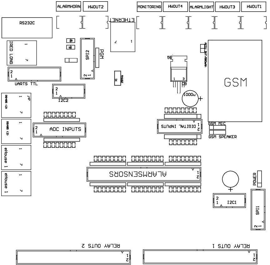 Lead Intelligent Ethernet controllers CommManager eHouse home , LevelManager Output No. 1 . is marked with a square solder pad on the PCB and also an arrow on the cover. There is protection against reverse insertion of the female connector to the male socket.
The pins are numbered sequentially with columns priority :
______________________________________________________________________________
|
|
| 2 4 6 8 10 12 14 16 18 20 22 24 26 28 30 32 34 36 38 40 42 44 46 48 50
| 1 3 5 7 9 11 13 15 17 19 21 23 25 27 29 31 33 35 37 39 41 43 45 47 49
|
|_V _______________________________ _______________________________
ADC INPUTS – Analog/Digital Converters Inputs – Measurement (ADC INPUTS ) (0 ; 3,3V ) – Do not connect any external voltage (IDC – 20)
1 – Gnd / Ground ( 0V)
2 – Gnd / Ground ( 0V)
3 – ADC IN 0
4 – ADC IN 8
5 – ADC IN 1
6 – ADC IN 9
7 – ADC IN 2
8 – ADC IN 10
9 – ADC IN 3
10 – ADC IN 11
11 – ADC IN 4
12 – ADC IN 12
13 – ADC IN 5
14 – ADC IN 13
15 – ADC IN 6
16 – ADC IN 14
17 – ADC IN 7
18 – ADC IN 15
19 – VDD ( +3 , 3V ) – Requires a jumper to power the controller limiting current / temperature sensors for power ( resistor 100 OM )
20 – VDD ( +3 , 3V )
DIGITAL INPUTS DIRECT – Direct Digital inputs ( on / off ) for a short to ground or opening ( do not connect any external voltage ) (IDC – 16)
1 – Digital Input / Digital Input 1 *
2 – Digital Input / Digital Input 2 *
3 – Digital Input / Digital Input 3 *
4 – Digital Input / Digital Input 4 *
5 – Digital Input / Digital Input 5 *
6 – Digital Input / Digital Input 6 *
7 – Digital Input / Digital Input 7 *
8 – Digital Input / Digital Input 8 *
9 – Digital Input / Digital Input 9 *
10 – Digital Input / Digital Input 10 *
11 – Digital Input / Digital Input 11 *
12 – Digital Input / Digital Input 12 *
13 – Digital Input / Digital Input 13 *
14 – Digital Input / Digital Input 14 *
15 – Digital Input / Digital Input 15 *
16 – GND
* Inputs can be used depending on the type of controller . Do not connect the major drivers . May cause permanent damage to the system .
DIGITAL INPUTS EXTENDED – Extending Digital Inputs (0 ; 3 . 3V ) – ( On / Off) short to ground or opening ( do not connect any external voltage (IDC – 50pin ) ( Revision 2 )
1 – Digital Input / Digital Input 1
2 – Digital Input / Digital Input 2
3 – Digital Input / Digital Input 3
4 – Digital Input / Digital Input 4
5 – Digital Input / Digital Input 5
6 – Digital Input / Digital Input 6
7 – Digital Input / Digital Input 7
8 – Digital Input / Digital Input 8
9 – Digital Input / Digital Input 9
10 – Digital Input / Digital Input 10
11 – Digital Input / Digital Input 11
12 – Digital Input / Digital Input 12
13 – Digital Input / Digital Input 13
14 – Digital Input / Digital Input 14
15 – Digital Input / Digital Input 15
16 – Digital Input / Digital Input 16
17 – Digital Input / Digital Input 17
18 – Digital Input / Digital Input 18
19 – Digital Input / Digital Input 19
20 – Digital Input / Digital Input 20
21 – Digital Input / Digital Input 21
22 – Digital Input / Digital Input 22
23 – Digital Input / Digital Input 23
24 – Digital Input / Digital Input 24
25 – Digital Input / Digital Input 25
26 – Digital Input / Digital Input 26
27 – Digital Input / Digital Input 27
28 – Digital Input / Digital Input 28
29 – Digital Input / Digital Input 29
30 – Digital Input / Digital Input 30
31 – Digital Input / Digital Input 31
32 – Digital Input / Digital Input 32
33 – Digital Input / Digital Input 33
34 – Digital Input / Digital Input 34
35 – Digital Input / Digital Input 35
36 – Digital Input / Digital Input 36
37 – Digital Input / Digital Input 37
38 – Digital Input / Digital Input 38
39 – Digital Input / Digital Input 39
40 – Digital Input / Digital Input 40
41 – Digital Input / Digital Input 41
42 – Digital Input / Digital Input 42
43 – Digital Input / Digital Input 43
44 – Digital Input / Digital Input 44
45 – Digital Input / Digital Input 45
46 – Digital Input / Digital Input 46
47 – Digital Input / Digital Input 47
48 – Digital Input / Digital Input 48
49 – GND of the – to short the inputs
50 – GND of the – to short the inputs
Alternatively, some controllers (Rev. 1) may have 6 connectors IDC – 10 instead of IDC – 50 for connecting digital inputs .
DIGITAL INPUTS EXTENDED – Extending Digital Inputs (On / Off) ( 0 ; 3,3V ) short to ground or opening ( do not connect any external voltage (IDC – 10PIN )
1 – Digital Input / Digital Input 1 – (n * 8) +1
2 – Digital Input / Digital Input 2 – (n * 8) +2
3 – Digital Input / Digital Input 3 – – || – –
4 – Digital Input / Digital Input 4
5 – Digital Input / Digital Input 5
6 – Digital Input / Digital Input 6
7 – Digital Input / Digital Input 7
8 – Digital Input / Digital Input 8
9 – GND of the – to short the inputs
10 – GND of the – to short the inputs
DIGITAL OUTPUTS 1 ( Relays OUTS 1 ) – Digital outputs with relays drivers for direct connection of relay coil (IDC – 50 )
1 – VCCDRV – Overvoltage protection relay connected to a 12V relay coil ( diode to VCC relays)
2 – VCCDRV – Overvoltage protection relay connected to a 12V relay coil ( diode to VCC relays)
3 – Digital output for direct connection to the relay coil (12V / 20mA ) No . 1 – Drive one direction A ( for CM )
4 – Digital output for direct connection to the relay coil (12V / 20mA ) No . 2 – Drive one direction B ( for CM )
5 – Digital output for direct connection to the relay coil (12V / 20mA ) No . 3 – Drive 2 direction A ( for CM )
6 – Digital output for direct connection to the relay coil (12V / 20mA ) No . 4 – Drive 2 direction B ( for CM )
7 – Digital output for direct connection to the relay coil (12V / 20mA ) No . 5 – Drive 3 direction A ( for CM )
8 – Digital output for direct connection to the relay coil (12V / 20mA ) No . 6 – Drive 3 in direction B ( for CM )
9 – Digital output for direct connection to the relay coil (12V / 20mA ) No . 7 – Drive 4 direction A ( for CM )
10 – Digital output for direct connection to the relay coil (12V / 20mA ) No . 8 – Drive 4 direction B ( for CM )
11 – Digital output for direct connection to the relay coil (12V / 20mA ) No . 9 – Drive 5 direction A ( for CM )
12 – Digital output for direct connection to the relay coil (12V / 20mA ) No . 10 – Drive 5 direction B ( for CM )
13 – Digital output for direct connection to the relay coil (12V / 20mA ) No . 11 – Drive 6 direction A ( for CM )
14 – Digital output for direct connection to the relay coil (12V / 20mA ) No . 12 – Drive 6 direction B ( for CM )
15 – Digital output for direct connection to the relay coil (12V / 20mA ) No . 13 – Drive 7 direction A ( for CM )
16 – Digital output for direct connection to the relay coil (12V / 20mA ) No . 14 – Drive 7 direction B ( for CM )
17 – Digital output for direct connection to the relay coil (12V / 20mA ) No . 15 – Drive 8 direction A ( for CM )
18 – Digital output for direct connection to the relay coil (12V / 20mA ) No . 16 – Drive 8 direction B ( for CM )
19 – Digital output for direct connection to the relay coil (12V / 20mA ) No . 17 – Drive 9 direction A ( for CM )
20 – Digital output for direct connection to the relay coil (12V / 20mA ) No . 18 – Drive 9 direction B ( for CM )
21 – Digital output for direct connection to the relay coil (12V / 20mA ) No . 19 – Drive 10 direction A ( for CM )
22 – Digital output for direct connection to the relay coil (12V / 20mA ) No . 20 – Drive 10 direction B ( for CM )
23 – Digital output for direct connection to the relay coil (12V / 20mA ) No . 21 – Drive 11 direction A ( for CM )
24 – Digital output for direct connection to the relay coil (12V / 20mA ) No . 22 – Drive 11 direction B ( for CM )
25 – Digital output for direct connection to the relay coil (12V / 20mA ) No . 23 – Drive 12 direction A ( for CM )
26 – Digital output for direct connection to the relay coil (12V / 20mA ) No . 24 – Drive 12 direction B ( for CM )
27 – Digital output for direct connection to the relay coil (12V / 20mA ) No . 25 – Drive 13 direction A ( for CM )
28 – Digital output for direct connection to the relay coil (12V / 20mA ) No . 26 – Drive 13 direction B ( for CM )
29 – Digital output for direct connection to the relay coil (12V / 20mA ) No . 27 – Drive 14 direction A ( for CM )
30 – Digital output for direct connection to the relay coil (12V / 20mA ) No . 28 – Drive 14 direction B ( for CM )
31 – Digital output for direct connection to the relay coil (12V / 20mA ) No . 29 – Drive 15 direction A ( for CM )
32 – Digital output for direct connection to the relay coil (12V / 20mA ) No . 30 – Drive 15 direction B ( for CM )
33 – Digital output for direct connection to the relay coil (12V / 20mA ) No . 31 – Drive 16 direction A ( for CM )
34 – Digital output for direct connection to the relay coil (12V / 20mA ) No . 32 – Drive 16 direction B ( for CM )
35 – Digital output for direct connection to the relay coil (12V / 20mA ) No . 33 – Drive 17 direction A ( for CM )
36 – Digital output for direct connection to the relay coil (12V / 20mA ) No . 34 – Drive 17 direction B ( for CM )
37 – Digital output for direct connection to the relay coil (12V / 20mA ) No . 35 – Drive 18 direction A ( for CM )
38 – Digital output for direct connection to the relay coil (12V / 20mA ) No . 36 – Drive 18 direction B ( for CM )
39 – Digital output for direct connection to the relay coil (12V / 20mA ) No . 37 – Drive 19 direction A ( for CM )
40 – Digital output for direct connection to the relay coil (12V / 20mA ) No . 38 – Drive 19 direction B ( for CM )
41 – Digital output for direct connection to the relay coil (12V / 20mA ) No . 39 – Drive 20 direction A ( for CM )
42 – Digital output for direct connection to the relay coil (12V / 20mA ) No . 40 – Drive 20 direction B ( for CM )
43 – Digital output for direct connection to the relay coil (12V / 20mA ) No . 41 – Drive 21 direction A ( for CM )
44 – Digital output for direct connection to the relay coil (12V / 20mA ) No . 42 – Drive 21 direction B ( for CM )
45 – GND / 0V
46 – GND / 0V
47 – GND / 0V
48 – 1 PWM ( PWM dimmer output 1 or red TTL – without power driver ) 3 . 3V / 10mA ( for control LED driver optocoupler transmit power)
49 – PWM 2 (Output 2 PWM dimmer or green TTL – without power driver ) 3 . 3V / 10mA ( for control LED driver optocoupler transmit power)
50 – 3 PWM ( PWM dimmer output 3 or blue TTL – without power driver ) 3 . 3V / 10mA ( for control LED driver optocoupler transmit power)
DIGITAL OUTPUTS 2 ( Relays OUTS 2 ) – Digital outputs with relays drivers for direct connection of a relay coil (IDC – 50 )
1 – VCCDRV – Overvoltage protection relay connected to a 12V relay coil ( diode to VCC relays)
2 – VCCDRV – Overvoltage protection relay connected to a 12V relay coil ( diode to VCC relays)
3 – Digital output for direct connection to the relay coil (12V / 20mA ) No . 43 – Drive 22 direction A ( for CM )
4 – Digital output for direct connection to the relay coil (12V / 20mA ) No . 44 – Drive 22 direction B ( for CM )
5 – Digital output for direct connection to the relay coil (12V / 20mA ) No . 45 – Drive 23 direction A ( for CM )
6 – Digital output for direct connection to the relay coil (12V / 20mA ) No . 46 – Drive 23 direction B ( for CM )
7 – Digital output for direct connection to the relay coil (12V / 20mA ) No . 47 – Drive 24 direction A ( for CM )
8 – Digital output for direct connection to the relay coil (12V / 20mA ) No . 48 – Drive 24 direction B ( for CM )
9 – Digital output for direct connection to the relay coil (12V / 20mA ) No . 49 – Drive 25 direction A ( for CM )
10 – Digital output for direct connection to the relay coil (12V / 20mA ) No . 50 – Drive 25 direction B ( for CM )
11 – Digital output for direct connection to the relay coil (12V / 20mA ) No . 51 – Drive 26 direction A ( for CM )
12 – Digital output for direct connection to the relay coil (12V / 20mA ) No . 52 – Drive 26 direction B ( for CM )
13 – Digital output for direct connection to the relay coil (12V / 20mA ) No . 53 – Drive 27 direction A ( for CM )
14 – Digital output for direct connection to the relay coil (12V / 20mA ) No . 54 – Drive 27 direction B ( for CM )
15 – Digital output for direct connection to the relay coil (12V / 20mA ) No . 55 – Drive 28 direction A ( for CM )
16 – Digital output for direct connection to the relay coil (12V / 20mA ) No . 56 – Drive 28 direction B ( for CM )
17 – Digital output for direct connection to the relay coil (12V / 20mA ) No . 57 – Drive 29 direction A ( for CM )
18 – Digital output for direct connection to the relay coil (12V / 20mA ) No . 58 – Drive 29 direction B ( for CM )
19 – Digital output for direct connection to the relay coil (12V / 20mA ) No . 59 – Drive 30 direction A ( for CM )
20 – Digital output for direct connection to the relay coil (12V / 20mA ) No . 60 – Drive 30 direction B ( for CM )
21 – Digital output for direct connection to the relay coil (12V / 20mA ) No . 61 – Drive 31 direction A ( for CM )
22 – Digital output for direct connection to the relay coil (12V / 20mA ) No . 62 – Drive 31 direction B ( for CM )
23 – Digital output for direct connection to the relay coil (12V / 20mA ) No . 63 – Drive 32 direction A ( for CM )
24 – Digital output for direct connection to the relay coil (12V / 20mA ) No . 64 – Drive 32 direction B ( for CM )
25 – Digital output for direct connection to the relay coil (12V / 20mA ) No . 65 – Drive 33 direction A ( for CM )
26 – Digital output for direct connection to the relay coil (12V / 20mA ) No . 66 – Drive 33 direction B ( for CM )
27 – Digital output for direct connection to the relay coil (12V / 20mA ) No . 67 – Drive 34 direction A ( for CM )
28 – Digital output for direct connection to the relay coil (12V / 20mA ) No . 68 – Drive 34 direction B ( for CM )
29 – Digital output for direct connection to the relay coil (12V / 20mA ) No . 69 – Drive 35 direction A ( for CM )
30 – Digital output for direct connection to the relay coil (12V / 20mA ) No . 70 – Drive 35 direction B ( for CM )
31 – Digital output for direct connection to the relay coil (12V / 20mA ) No . 71 – Drive 36 direction A ( for CM )
32 – Digital output for direct connection to the relay coil (12V / 20mA ) No . 72 – Drive 36 direction B ( for CM )
33 – Digital output for direct connection to the relay coil (12V / 20mA ) No . 73 – Drive 37 direction A ( for CM )
34 – Digital output for direct connection to the relay coil (12V / 20mA ) No . 74 – Drive 37 direction B ( for CM )
35 – Digital output for direct connection to the relay coil (12V / 20mA ) No . 75 – Drive 38 direction A ( for CM )
36 – Digital output for direct connection to the relay coil (12V / 20mA ) No . 76 – Drive 38 direction B ( for CM )
37 – Digital output for direct connection to the relay coil (12V / 20mA ) No . 77 – Drive 39 direction A ( for CM )
38 – Digital output for direct connection to the relay coil (12V / 20mA ) No . 78 – Drive 39 direction B ( for CM )
39 – Digital output for direct connection to the relay coil (12V / 20mA ) No . 79 – Drive 40 direction A ( for CM )
40 – Digital output for direct connection to the relay coil (12V / 20mA ) No . 80 – Drive 40 direction B ( for CM )
41 – GND / 0V
42 – GND / 0V
43 – GND / 0V
44 – GND / 0V
45 – PWM 1 (PWM dimmer Output power driver 1 or red 12V / 1A)
46 – PWM 1 (PWM dimmer Output power driver 1 or red 12V / 1A)
47 – PWM 2 (PWM dimmer Output power driver 2 or green 12v / 1A)
48 – PWM 2 (PWM dimmer Output power driver 2 or green 12v / 1A)
49 – PWM 3 (PWM dimmer Output power driver 3 or blue 12v / 1A)
50 – PWM 3 (PWM dimmer Output power driver 3 or blue 12v / 1A)
POWER DC ( 4 – PIN Socket ) Power
1 – Power supply ( + 5V / 2A for the GSM module )
2 – GND / Ground / 0V
3 – GND / Ground / 0V
4 – Power supply ( +5 to +12 V ) / 0.5A ( Power of controller) UPSed – with accumulator (optional)
ETHERNET – RJ45 LAN Jack for LAN ( 10Mbs )
Standard
ACCU – Battery (3 . 7V / 600mAh ) for GSM module
1 + Battery
2 – GND
eHouse 1 – (RJ45) connector for connection to the bus system eHouse 1 (RS – 485) when installing Hybrid (only CM )
1 , 2 – GND / Ground ( 0V)
3 , 4 – VCC + 12V , connected to the power supply controller (not connected – cut wires )
5 – TX + ( Transmit output non inverting ) Differential
6 – TX – ( Transmit output inverting) Differential
7 – RX – (Receive inverting input ) Differential
8 – RX + (Receive non-inverting input ) Differential
the connector is identical to the standard RoomManager, ExternalManager, HeatManager so it requires cross eHouse1 bus cable:
- TX + RX +
- TX – RX –
- RX + TX +
- RX – TX –
HWOUT1 , HWOUT2 , HWOUT3 , HWOUT4 , ALARMLIGHT , ALARMMONITORING , ALARMHORN – Protected outputs relays ( relay ( Normally Closed , common , Normally Open ) (Applies CM )
ALARMLIGHT – Lighting warning alarm for CM
ALARMHORN – Siren for CM
ALARMMONITORING – Control output for alarm monitoring radio links for CM
HWOUTx – Outputs Dedicated hardware drivers (future use )
Contacts connectors numbered from left to right
- 1 – NC Normally Closed – shorten to COM without powering relay coil,
- 2 – COM – Common,
- 3 – NO normally open – shorten to COM when powering relay coil.
I2C1 , I2C2 , SPI1 , SPI2 , UARTS TTL , PGM – expansion Slots
Do not connect external devices. Interfaces of different variants eHouse controllers. Connection to other signals may damage controllers.
These pins are shorted to pin digital inputs, analog , digital outputs directly on the processor without any protection.
For more information : Smart House eHouse – Ethernet Driver Drives and Alarm Smart House eHouse – Ethernet Floors driver or flat
Buy It:
Smart Home – drives control and security system
inteligentny dom – sterowanie roletami + alarm