eHouse.PRO smart home modules
eHouse.PRO Smart Home is a professional building automation system which allows very easy installation and do it yourself connection .
eHouse.Pro Smart House consists of the following electronic modules:
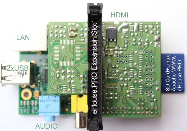
1 ) Linux microcomputer (CPU) with extension module and interfaces .
In addition to connecting the I / O modules eHouse.PRO can also contain :
- RTC
- CAN gateway – RS232 for eHouse4CAN
- RS-232 <=> RS-485 for eHouse One
- Switching Power Supply 24-12VDC/5VDC/2A
The intelligent building “eHouse One” and “eHouse4CAN” is connected to the flat cable IDC-20 , However, detailed description of these versions is not included in this post.
All modules of eHouse.Pro smart home connects with shortest IDC-40 flat tape.
The module is connected to a LAN cable (Ethernet) with standard RJ-45 to WiFi switch or router.
eHouse.Pro Smart home supplies are connecting 5V/2A mini USB connector – located on microcomputer board.
For the test phase and commissioning can also be connected to the HDMI monitor or TV .
eHouse.PRO Intelligent I/O modules
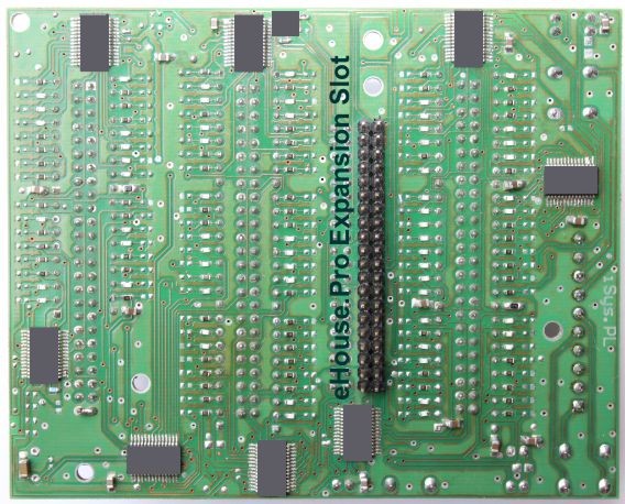
Each I/O module has two connectors IDC-40 (connected to each other) on the bottom and the top layer of the PCB, so it can be installed in 2 ways .
1 ) The modules can be arranged vertically (one above the other using short wires ~ 5cm from both sides terminated with IDC-40). For each I/O module one IDC-40 tape is needed :
– for 2 modules ( 128 inputs and 128 outputs) need 2 tape
– for 4 modules (2 * 128 inputs and 2 *128 outputs ) need 4 tapes .
Due to this , that flat tape carried fast, short-range interfaces for high-speed operation it is recommended not to extend the straps connecting the modules.
It may cause communication errors , the need to retransmit data or malfunctioning electronics.
In this case eHouse.Pro system modules can be enclosed in a single box 12cm*12cm*12cm , and externally output only cables: LAN , IDC-50 tapes for inputs and outputs , and power supply.
2 ) The second option is worse than the first because it requires a longer IDC-40 cable than the first. The modules can be located next to each other and to be connected to a single flat belt IDC – 40 with clenched IDC connectors – 40 at a minimum distance to allow free distribution of the modules .
However, this distance is about 3 times bigger than in the first (ca.. 15 cm between each plug in) which gives 30cm to 2 I/O modules ( 3 plugs ) and 60 cm for 4 I/O modules (5 plugs) . Please be sure to check the operation of the system (and logs) for at least a week if there are communication problems resulting from long cables IDC-40 .
eHouse.PRO Intelligent digital input (on/off )
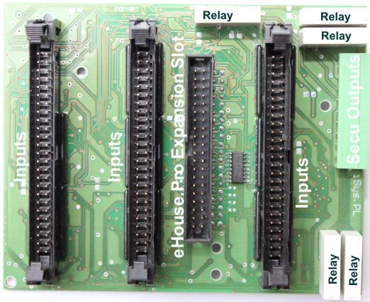
IDC-50 are used to connect digital inputs and have pin compatible with the CommManager inputs and Expander Inputs (48 ) .
It is very favorable when it comes to the wiring conductors of alarm sensors telephone RJ-12 (6pin) and connecting the digital inputs throughout the home over long distances.
IDC-50 tape length is not critical and can be as much as 30MB .
10 pin connector connecitonlines relay contacts alarm system (Horn , Warning , EarlyWarning , Silent – quiet alarm , monitoring – radio monitoring ) are available directly from eHouse.PRO system .
40-pin connector (for connecting eHouse.PRO smart home modules) we can use the lower, Top or both if desired.
eHouse.Pro Intelligent digital output ( on/off )
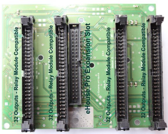
IDC – 50 are used to connect the digital outputs (on/off) and have a pin connectors compatible relay modules on DIN rail.
They contain drivers relays and surge protectors.
Output Connectors IDC-50 can be connected as described smart home eHouse performance switching professional .
IDC-50 Tape length is not critical and can be as much as 20m .
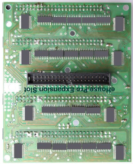
40-pin connector (for connecting eHouse.PRO smart home modules) we can use the bottom or top of the PCB or both if desired .