RS-485 eHouse Home Automation controller installation RoomManager – do it yourself
Smart Home eHouse RS-485 standalone installation of RoomManager in controlled room .
In this post we will describe the easiest way to connect and install the RoomManager in RS-485 version.
This post is an extension of articles electronic house RS-485 eHouse – connect the outputs to a mini – switching board for ease of installation to verify the self-assembly.
Low voltage installation , connect all cables, assemblage switching is accomplished in a total by 10 years child under the supervision of an adult. Only mount boxes , wiring in the home position , connection of power receivers and equipment 230V requires a qualified electrician.
The description is intended not only for installers but also amateurs, who do not have special abilities and talents in the field of electrical and electronics .
For “Do It Yourself” install at home even children can be very helpful, which will certainly consider it as an interesting DIY job and escape from blocks, smarphones, pads, television or computer games. Based on our own experience, 10 year child can perform these tasks at a similar time and as accurately as adult.
eHouse system drivers have a very large amount of hardware resources (inputs , outputs) – about 80.
For quick and easy assemble and disassemble the controller and ensure correct operation for decades using eHouse system, it uses IDC sockets of different sizes in order to prevent error and exchange plugins during install and uninstall the driver.
IDC couplings are dedicated for flat tape (like old IDE hard drive ) with different amounts of pins , eg. 10 , 14 , 16 , 20 , 40 , 50.
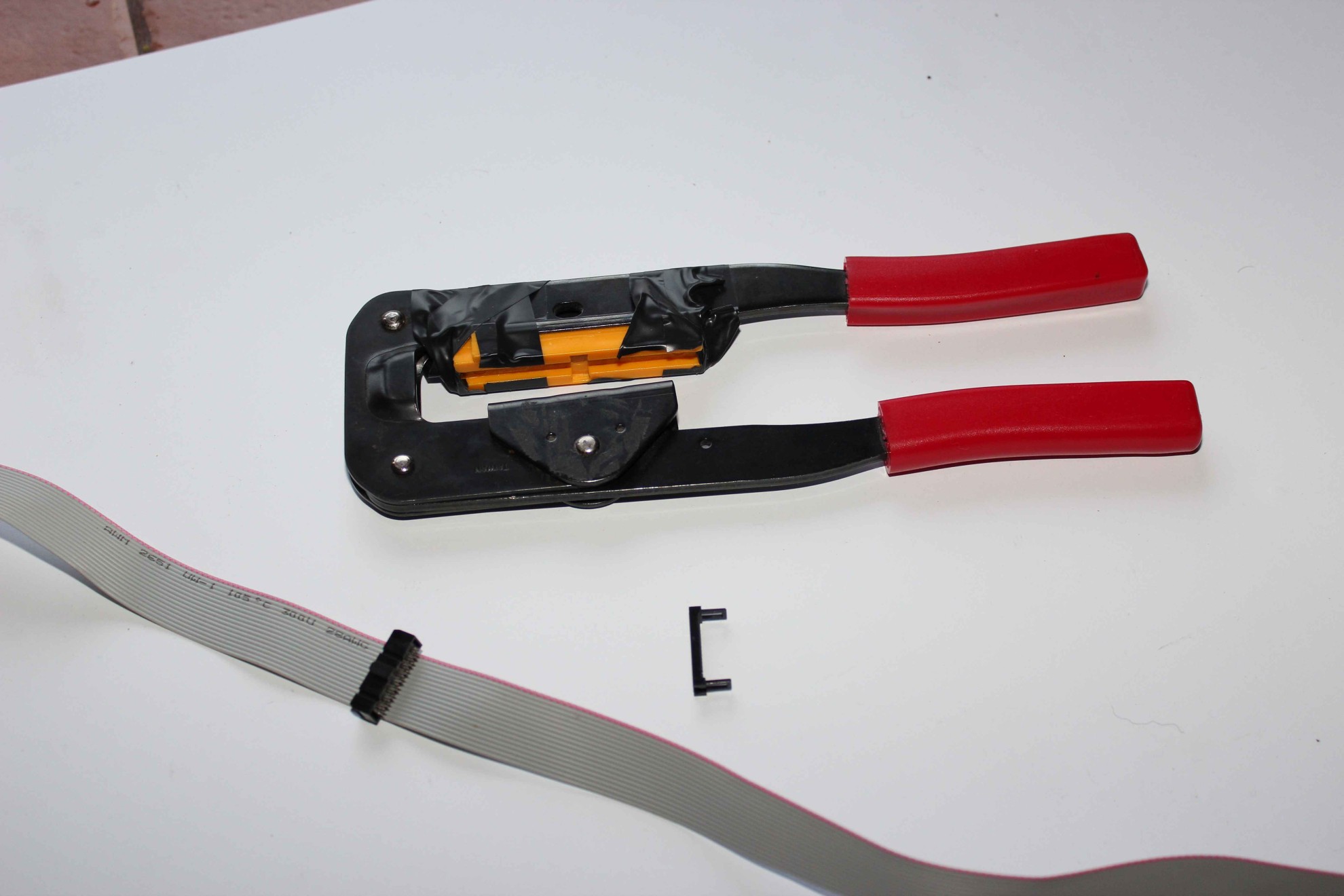
To install the entire eHouse system – IDC crimper should be bought at a price about 30$ who repeatedly speed up assembly and is essential especially with the larger sizes of sockets ( 40,50 strips tapes).
Regardless of width the first pin of flat tape is marked (red, orange, etc.) is easy to determine from which side we want to exit. This is especially valuable when conducting wires in the walls over long distances. The tapes are sold in rolls of approximately 30mb regardless of the number of strips. Except analog sensors there is practically no technical limit to the length of the tape. However, due to its cost and 230V cables it should be optimized considering RM and switchboard location directly in areas controlled , which will significantly reduce the expenditures of low voltage cables, 230V wires, labor, time, etc..
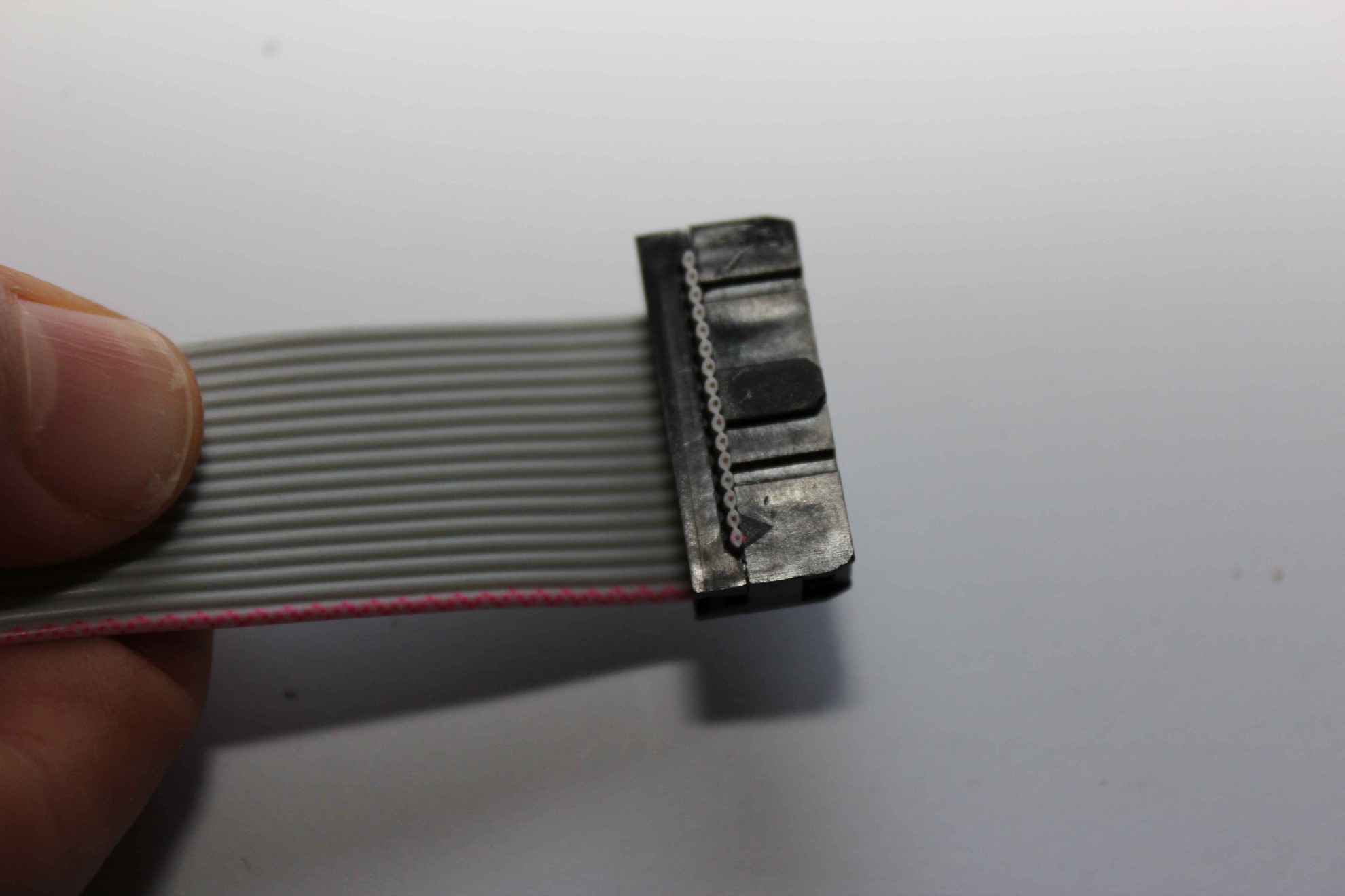
IDC of any size has a tab and indentation in the middle , and marked the first pin (usually a triangle ) on the same page .
This prevents the possibility of put it in wrong way (opposite) into connector or to connector with different amounts of pins, which significantly protects the driver from damage.
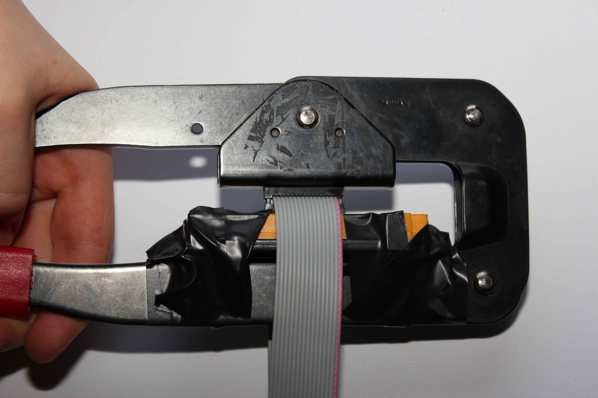
Before clamping IDC connectors for ribbon flat connector should be placed on the tube so , the arrow is the red wire (pin 1 ) . It does not matter which side of the cable let in , while maintaining the above relationship . 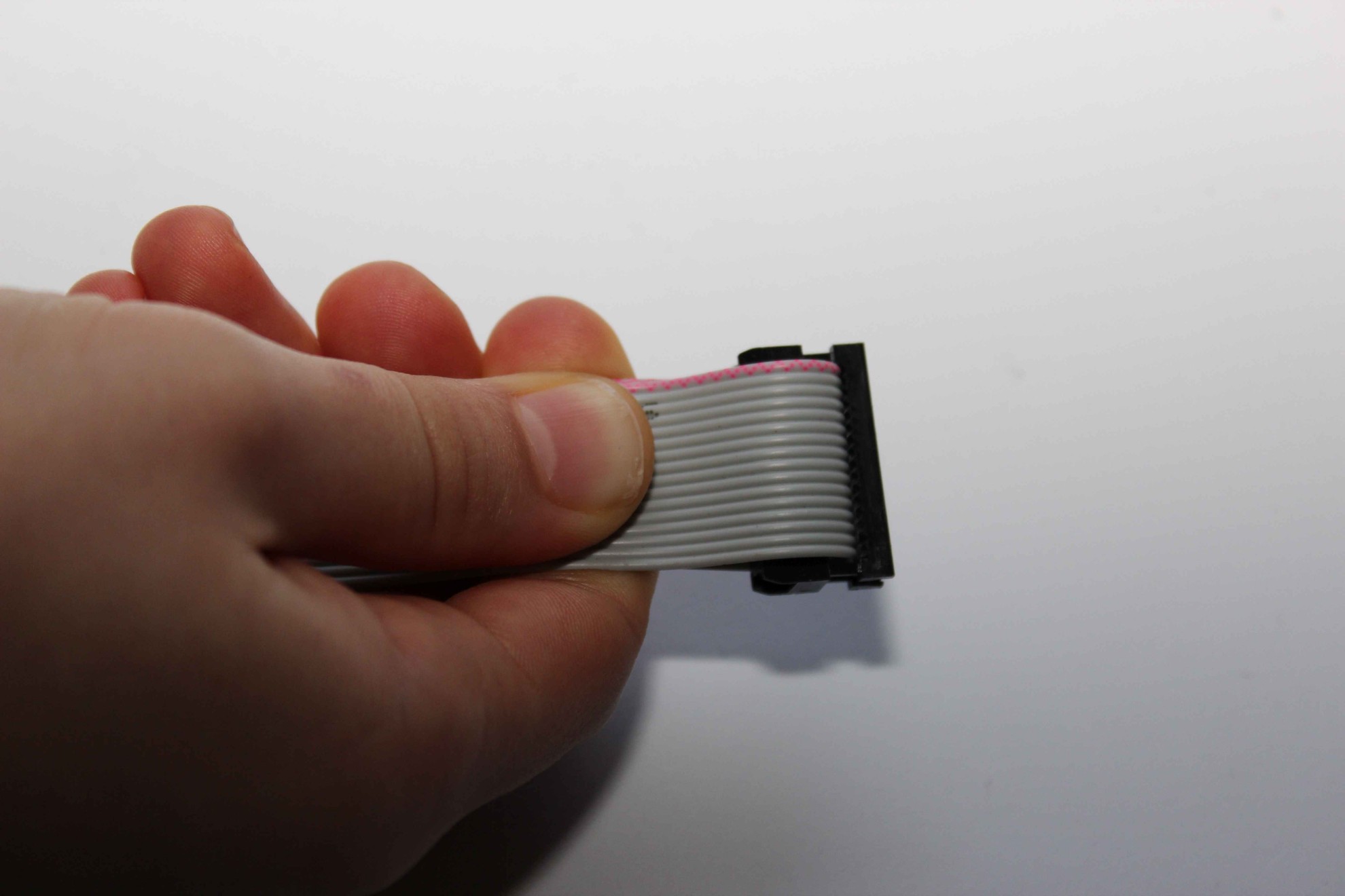 After completing the connector and the cable without crimping it is necessary to set the wire perpendicular to the connector . This is particularly critical with 20 and more strips when clamping pins can cause damage to cables , internal short circuit , etc..
This can be done :
- folding the tape folded in half
- applying squeezing tool to the edge of a table or other rectangular object , and along the perpendicular edge of the tape lay flat
- Cutting the cord perfectly perpendicular and then adjust the plug
The wires in the wall should have a few centimeters more. In case of incorrect tightening you could cut the connector and tighten the new one. Errors can arise not only from our side, but damage to the connector while clamping, damage to the wires in the wall and small margin allows us to implement “plan B”.
Before working on the long wires distributed in the wall, we recommend workout on a table at short distances and perform a few trials.
40 and 50 pin flat tape can be clamped before laying in the wall from the controller side, ohmmeter should measure whether the adjacent pins are not shorted together , and whether the appropriate number wires on both sides are connected to each other .
After placing the connector on the tape flat and inserted into the crimper , before tightening , make sure again that:
- the pin 1 wire goes to pin 1 of the connector
- the tube is arranged perpendicularly with respect to the connector
- whether the shape of a flat strip fits into notches on the connector on both sides
 After fulfilling all the above conditions , we can only push the lever crimping IDC .
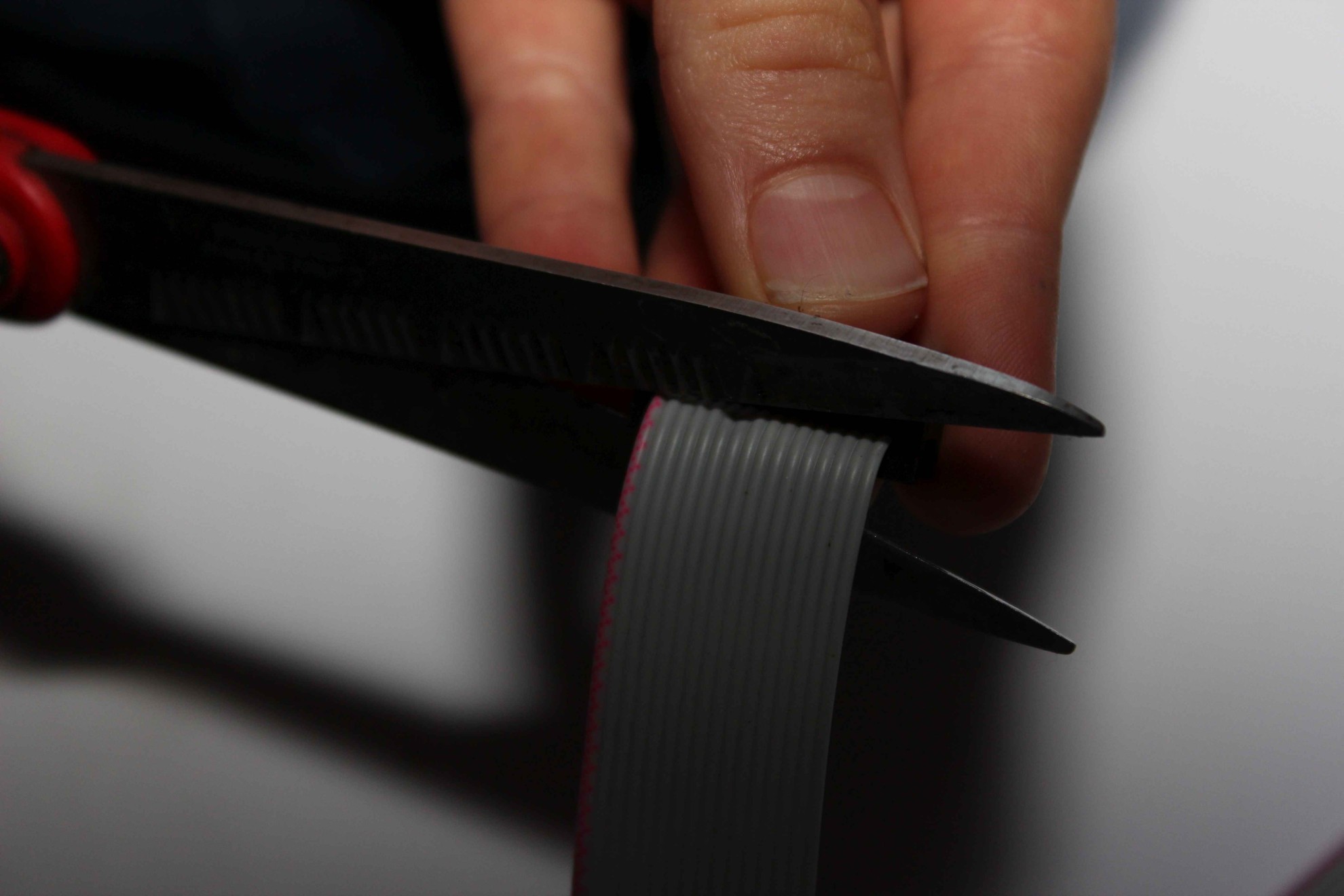
Excess cable should be cut off with sharp scissors at the junction of sufficient length to do it all at once on single cut.
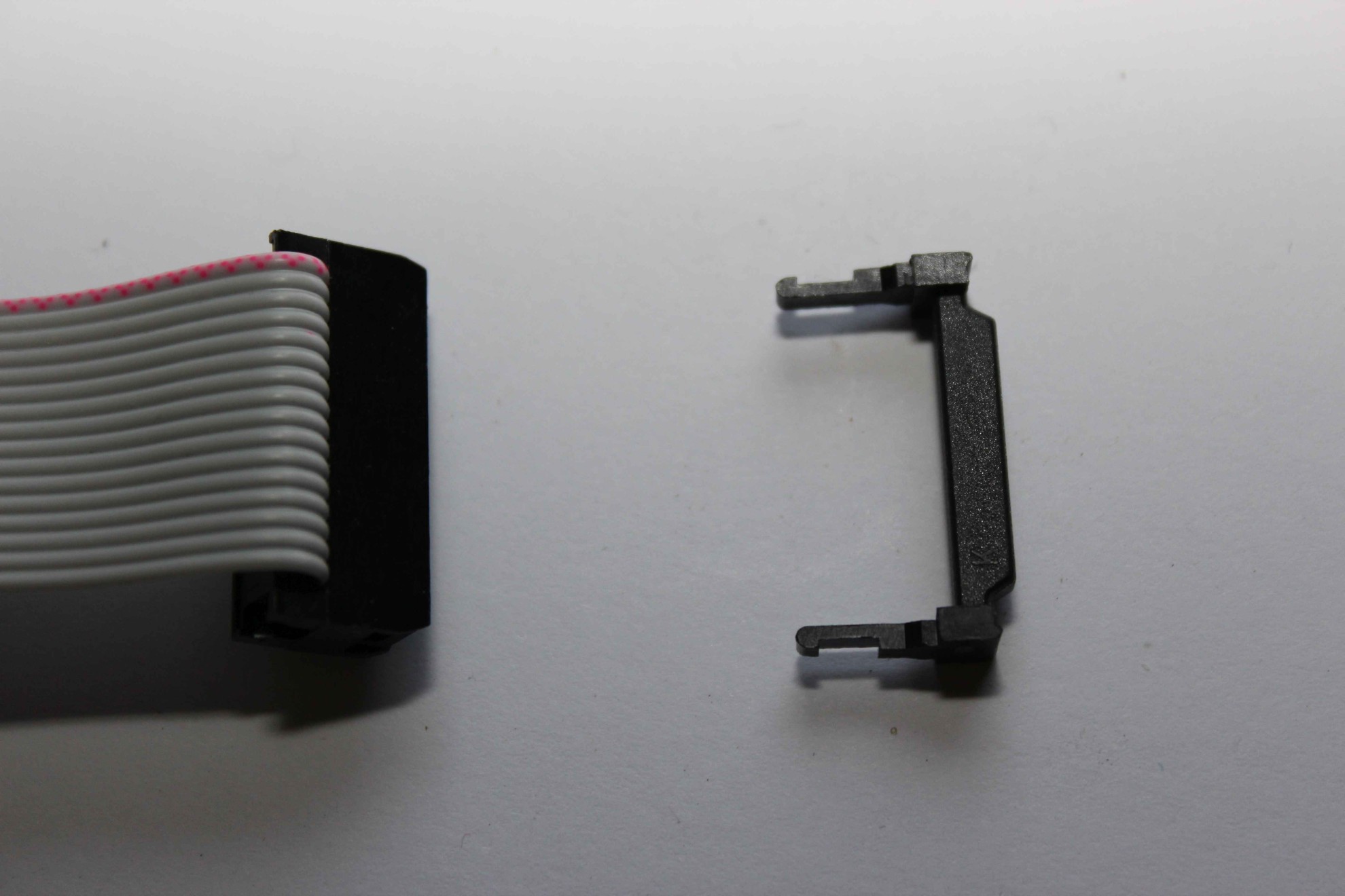
If you installed the cable in the wall is in the opposite direction to the connector mounted on the controller can add stopper , which simultaneously reinforces the connection .
Ideally, you should immediately lead wire so that once cable with plug fits directly to the driver and entered from the right side to the housing ( try on the controller ) . Manipulation of a flat belt in amounts of more than 20 pins is very difficult and cumbersome as 10cm section .
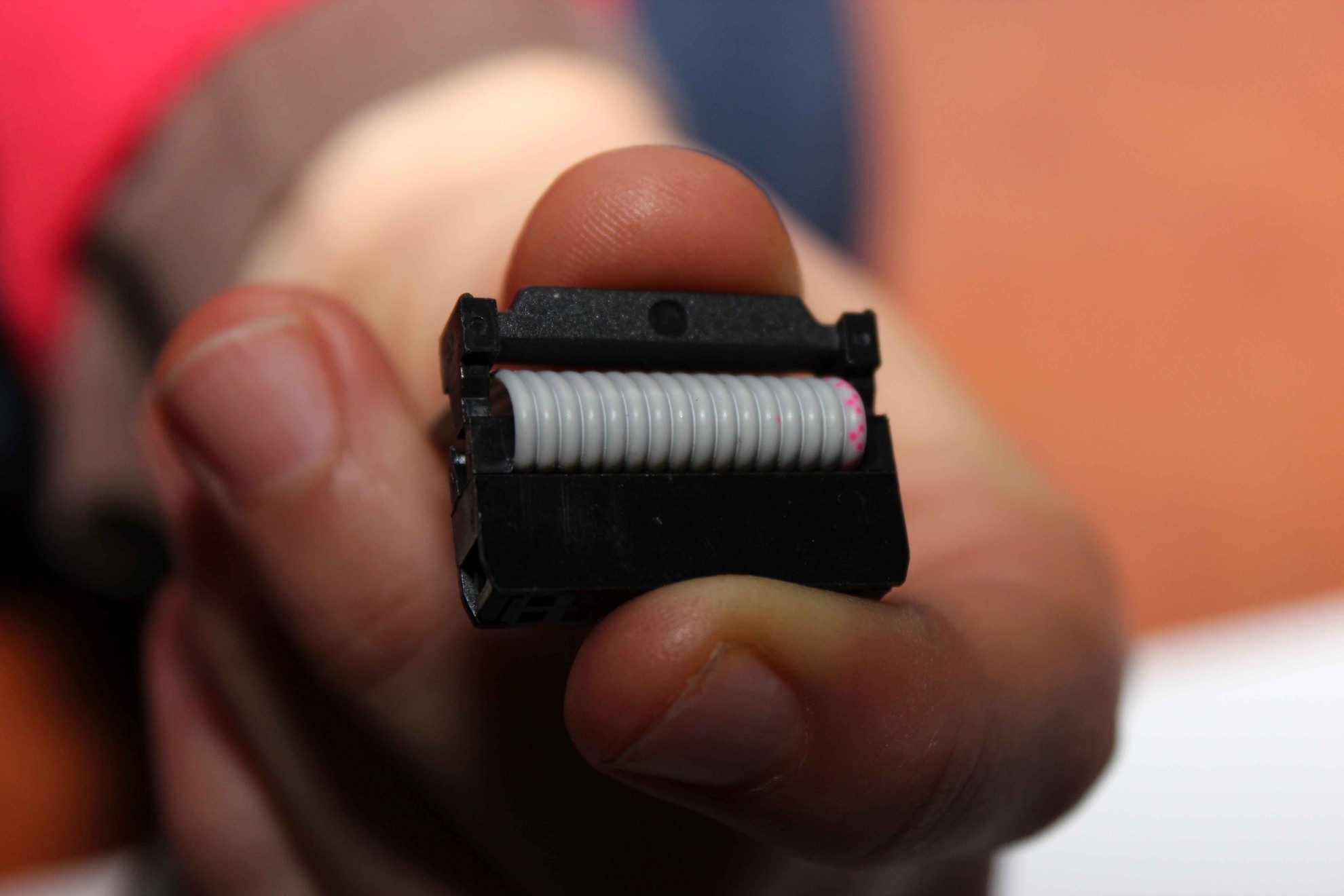
Keep in mind also , that in a few years it may be difficult to remove it after gluing the socket contacts and connectors . 40-50 Connectors pins must be absolutely tight and finished plugs and enter directly into the controller box without twisting , folding , rotation .
The following example uses the electrical box ( 5 fuses with window ) located on the opposite wall to HiFi equipment , TV , Sat , Audio – Video to be able to control infrared ceiling – about 1 meter from the wall perpendicular .
Despite the visibility of the box in the room is the simplest and quickest solution to implement , and most of the rooms for adoption . This location practically are not dependent on the room furniture and accessories , which may change after years with taste .
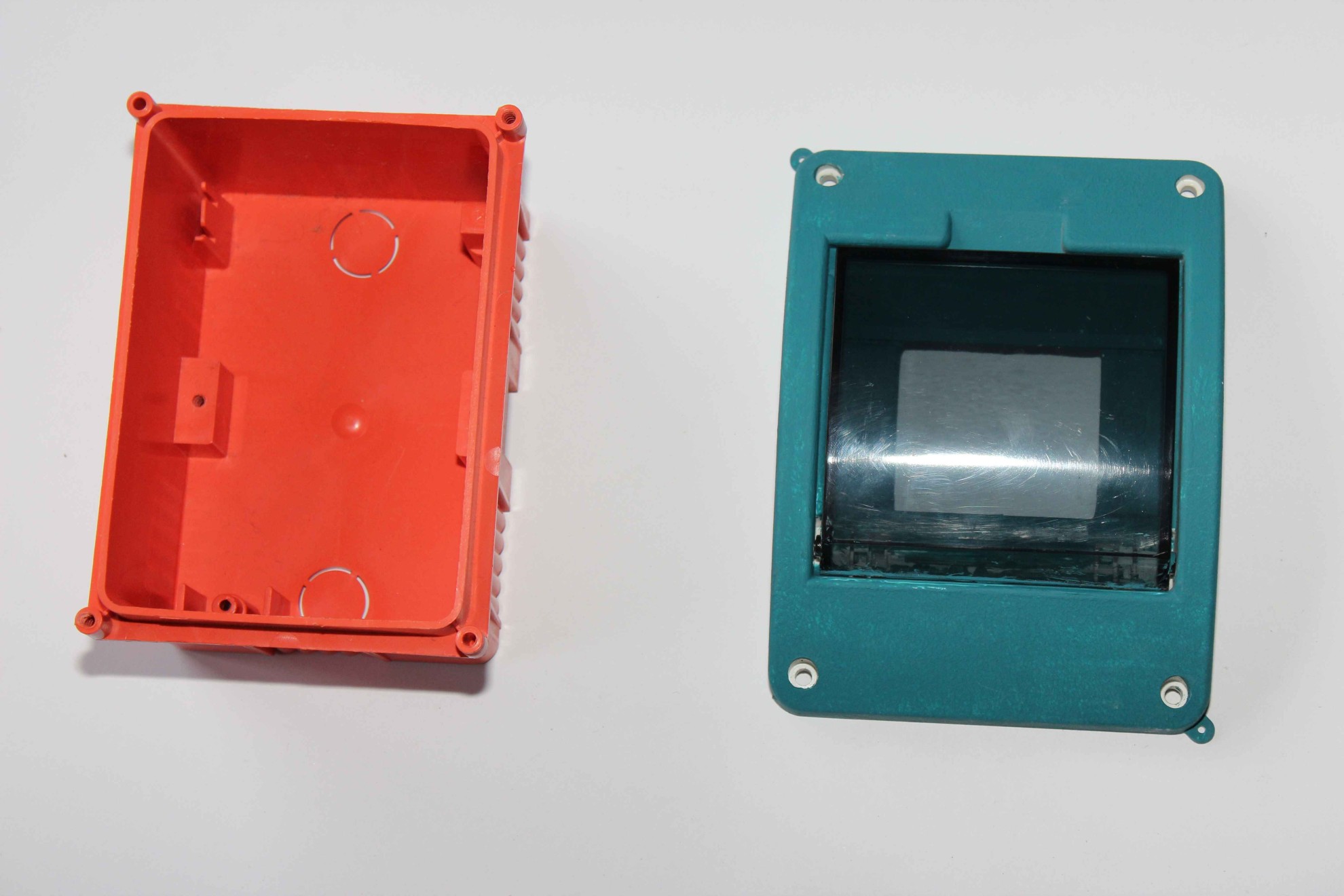
The top grille can be painted after removing ( and picture windows ) on the color of the walls during their painting as much mask the controller housing .
Transparent window is required for the installation of an infrared transmitter and receiver directly on the plate RoomManager and provides two-way communication and “visibility of devices” controller and managed.
Other housing , or their complete masking requires removal of the receiver and the transmitter outside the driver (or use external IR panel) if you intend to use these functions. It should also be borne in mind that in a few years you can change your mind and it’s better not block such a possibility .
To bring some accessories from the controller ( IR receiver , IR transmitter , light sensor , temperature , Dimmers ) tape is flat IDC – 16 for mounting an external panel or arrange .
Measuring inputs Other measuring inputs if used must be connected to the tape IDC-20 or 10 pin socket depending on ERM revision.
At a greater distance between the sensor and controller than 1 meter , use shielded cable to reduce the impact of interference . The use of flat cable over long distances is possible , however, constitutes acceptance of the larger measurement errors and disturbances and fluctuations ( “swimming” ) measured value in this case is absolutely essential to test the measurements after complete installation before applying the plaster .
It should be noted that unscreened wires act as an antenna receiving all signals and noise in the area . Faults are random (mobile phones , transmitters , radiolines , etc. ) and do not fully reflect all possible cases.
In the case of flat cable can be shielded with aluminum foil , where each segment is connected to the mass of the system. Shielded cable for each individual sensor , however, give much better results .
- The first two pins are a controller GND ( 0V ) which is connected to the ground of sensor (-) .
- The last two pins are VCC plus of power controller (3 . 3V ) protected against excessive consumption of electricity and used to power the sensor (+)
- Other pins are measuring inputs – connect the first one after the other odd
Is impermissible to connect external powered sensors . The sensors must be properly isolated from any external voltages , conductive elements , moisture , etc. .
RommManager requires incorporation ladder resistors in the connector on the controller board or the use of a single resistor between input and 3.3V to power the sensor for non powered sensors like LM335. Temperature Sensors LM335 work properly in this case only to 56 degrees ( require resistor Pull-Up 200 Ohm ) .
Digital inputs ( switches , sensors) are connected to the flat cable 14 pin .
The first two pins tape IDC – 14 are connected to the ground of controller (0V) . Other pins are further digital inputs. for IDC-16 connector please see pin specification.
Input activation occurs as a result short of the input by the switch, the ground of the reed sensor .
Is impermissible to connect external voltages to the inputs of the controller. The sensors must be properly insulated and isolated from any external voltages , conductive elements , moisture , etc. .
Tape for switches easiest stretch for about an entire room at the height of future switches outputting electrical box (cans) in the planned switches location. Follow the loop for a distance of about 10-15cm so that you can easily tighten the connector in cans. Flat tape should be terminated immediately IDC-14 connectors, as the controller side, which greatly facilitate the installation of wiring for switches .
RS-485 – Industrial serial bus
The controller is connected with standard UTP-8 cable ended RJ-45. Keeping of the standard colors of cables is very important because of the pair of wires ( twisted pair ) to minimalize distortion occurring in the wires and received by them, even at very high data transmission distances (tens of meters) .
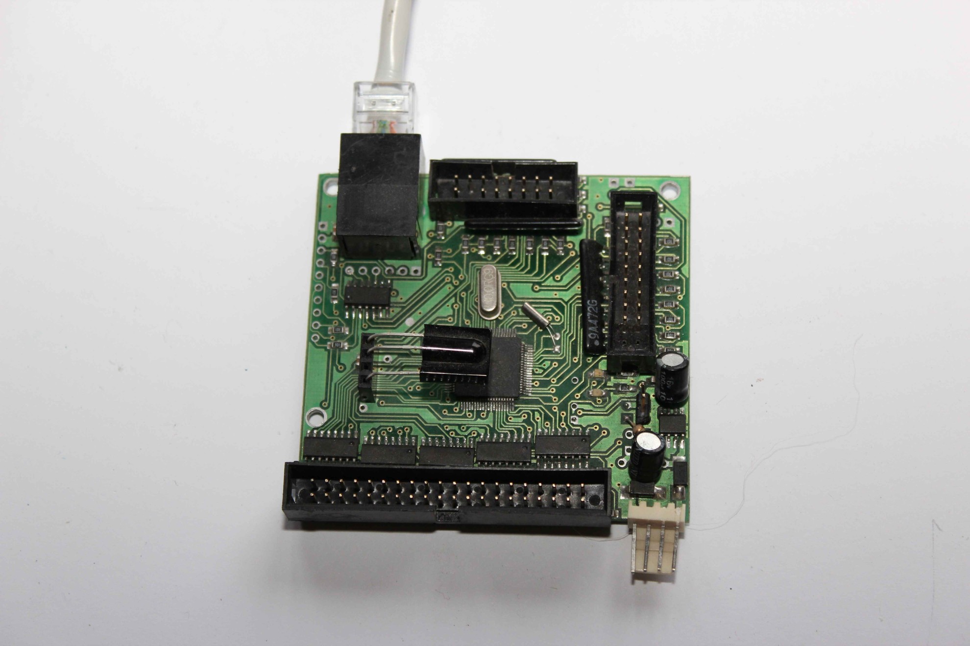
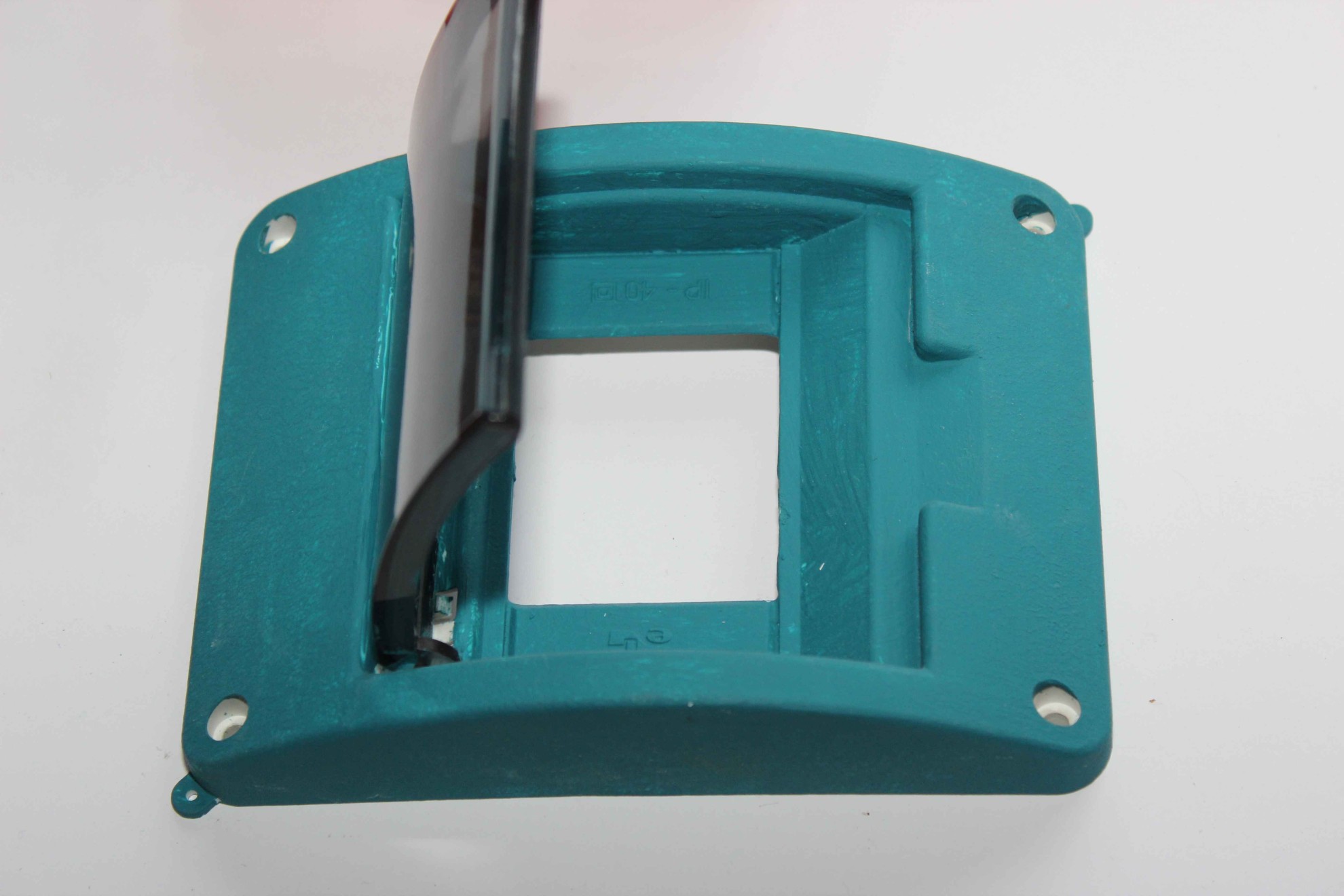
Orange concealed part is installed in a manner such as to enable ” flushing ” the future plaster . From the bottom or the sides cut out a large hole / holes for passing the flat tapes and other cables in order to immediately plug the connector into the controller . It is worth to try laying cables directly to the driver after his makeshift start .
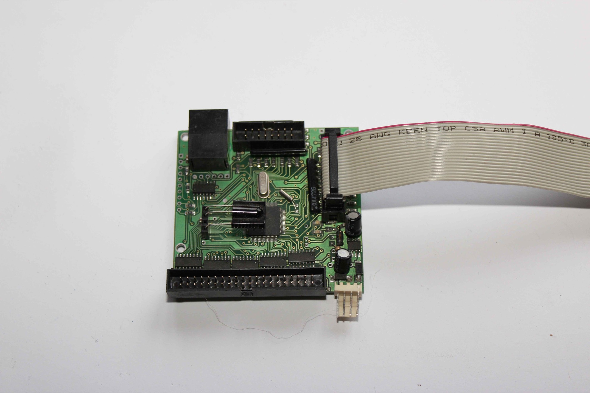
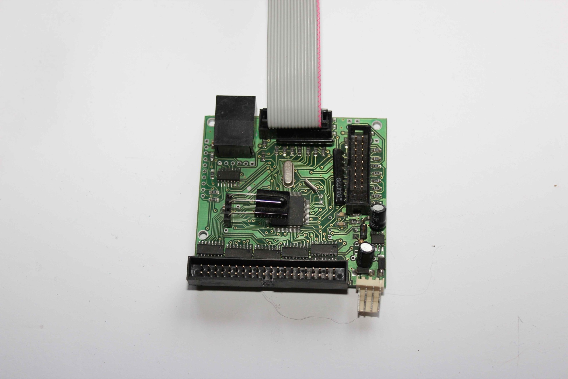
Completely connected RoomManager : 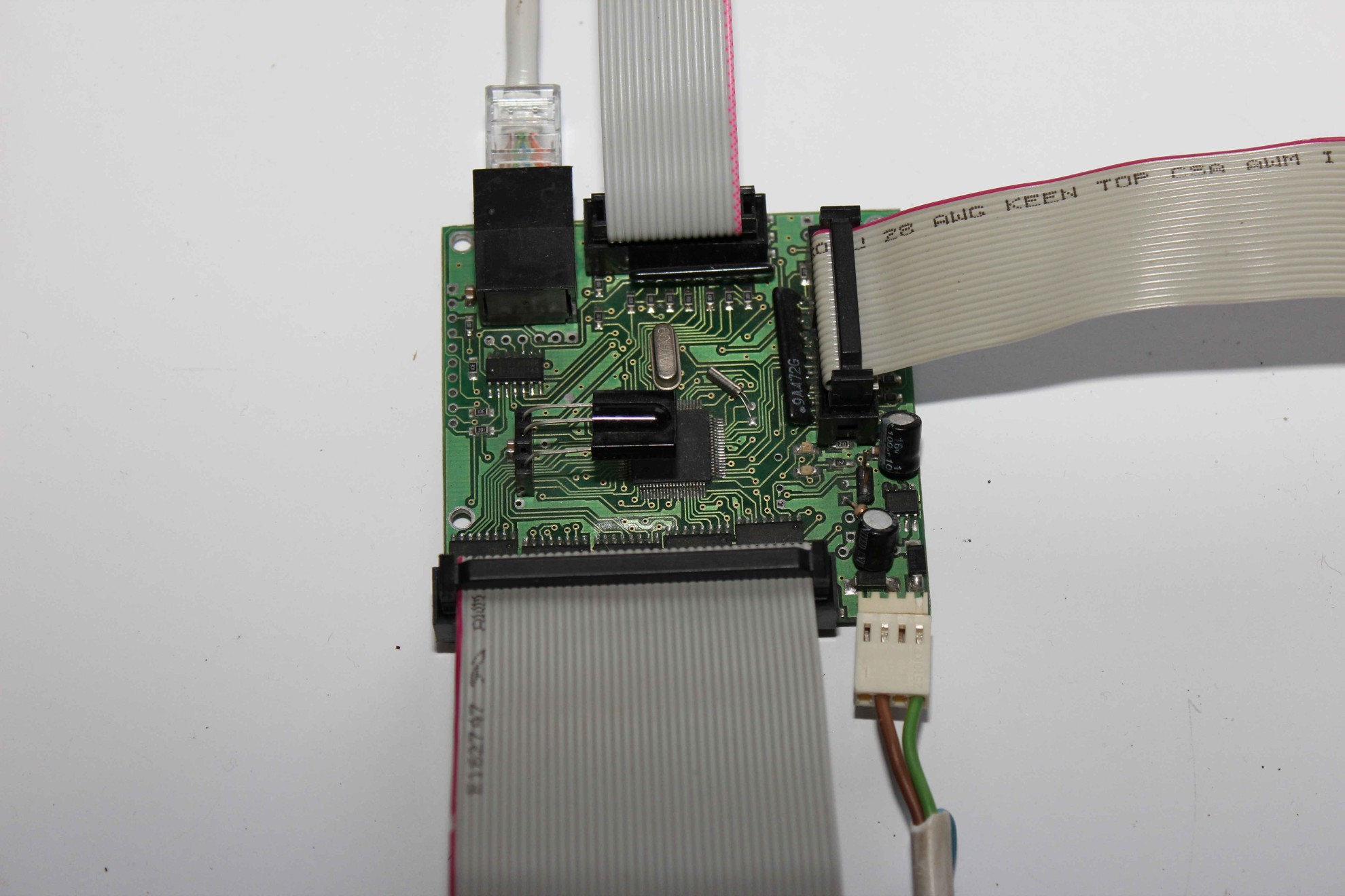
Arrangement of wires at the entrance to the electrical box should be to maximize simplify manipulation of the cable .
If you intend to use mounted infrared receiver and transmitter on board the RM twisted flat belt can effectively prevent the transmission and reception of covering sensors .
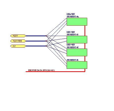
Wiring diagram of the various segments of the eHouse system power supply is shown below :