eHouse 1 Electronic home mini switchboard self installation
Smart Home “eHouse 1” installation of a single segment of the system and a mini indoor switchboard controlled.
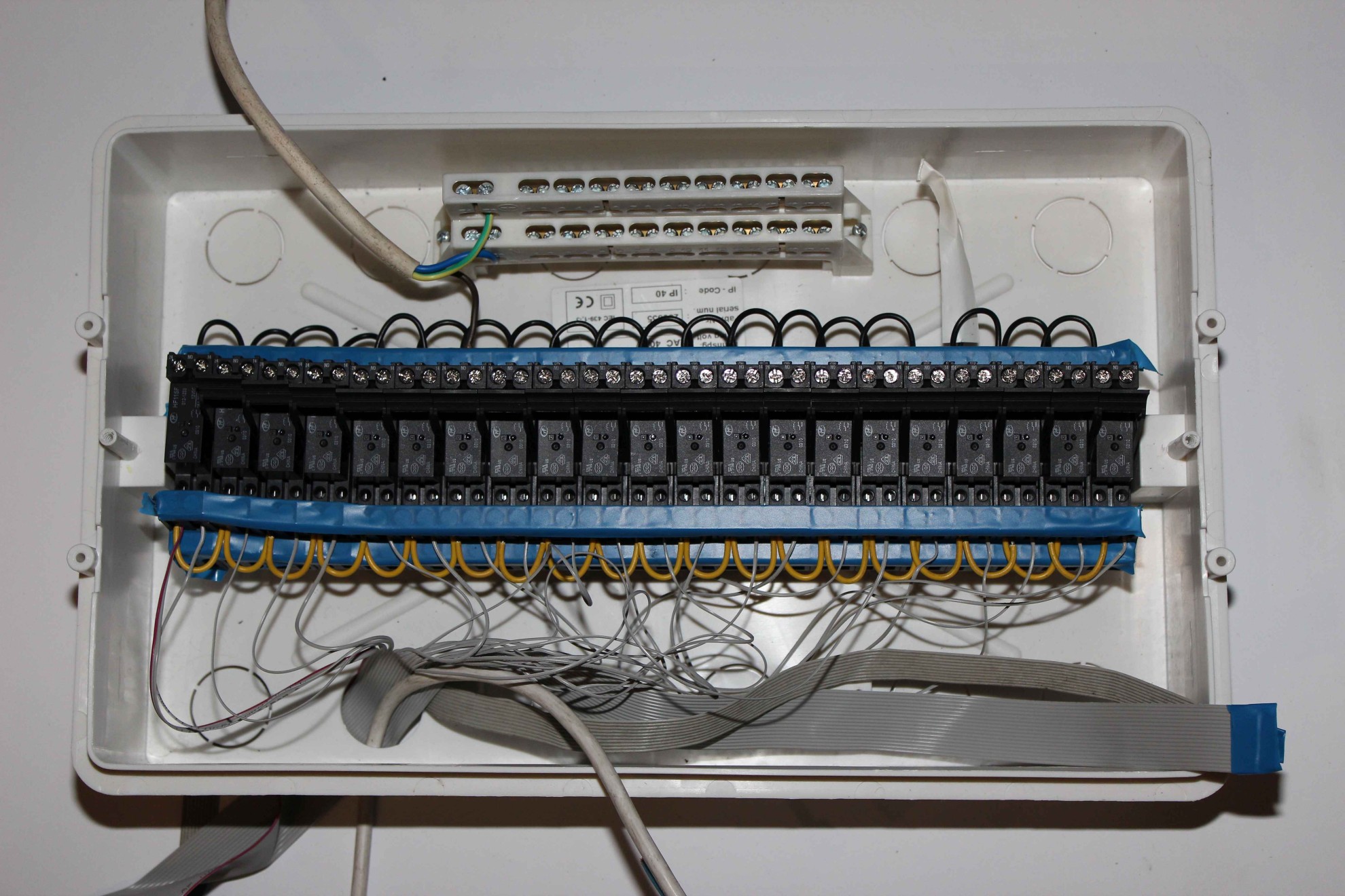
Connecting the controller to the relay outputs , receivers and power supply to the controller.
We are using standard fuses mounting boxes used for electric installations, eg. Moeller (BC-U-1/18-ECO ) (1 row , Concealed for 18 fuses).
Cover size depends on the number of relays, which we intend to use, and whether we are going to put RoomManager in one box with relays.
Number of standard relays is equal to number of fuses.
In addition, sometimes you can mount 2 to 3 relays more, But generally we cover in this way DIN rail mounting bolts to the box which is very inconvenient, as having access to it at the time , we removed all relays plastering along the rail after checking the installation done . Even if you are not going to disassemble them completely , we have much more leeway , to secure them before plastering , water , moisture , land , paints .
When installing RoomManager module in box it should be a minimum of 5-10 inches of clearance from all 230V wires and other external voltages.
If you wish to install the controllers in one box it should be 2 or 3 row box. To choose from on the market are having their cases to 12 or 18 ( fuses/relays) in a row.
Rows can be from 1 to 3. 1 row Boxes do not allow you to install the controller inside and in addition does not allow the use of all outputs of controllers .
To use the 24 starting drivers without installing the driver in the middle , need to install the box 2*12 ( min 2 rows and 12 relays) .
To use all controller outputs and install the controller in case it is necessary to apply the box 2*18 or 3*12.
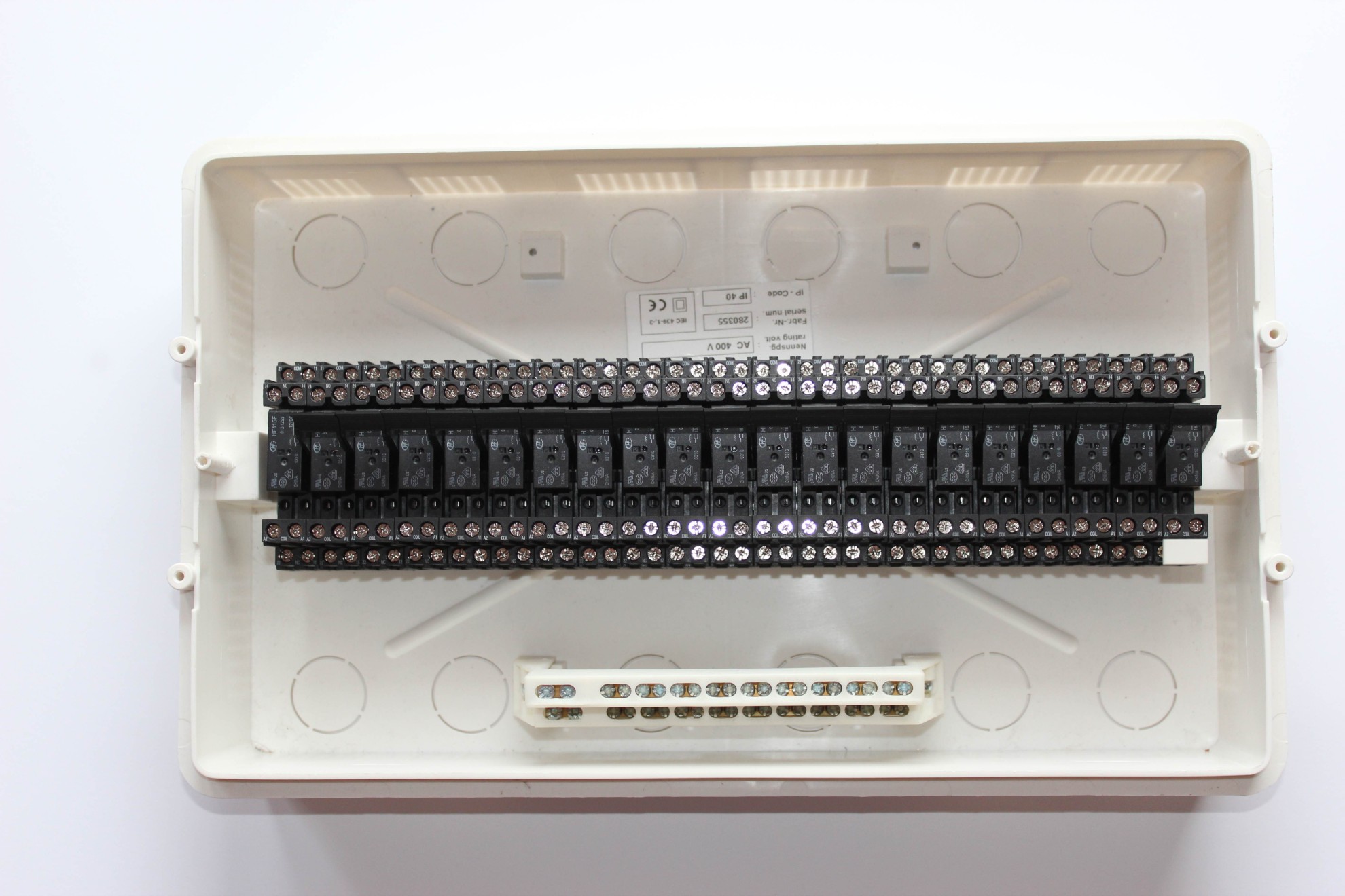
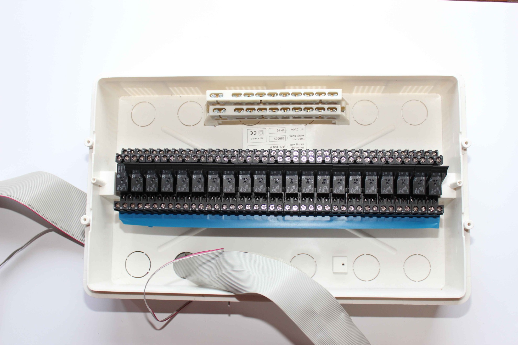
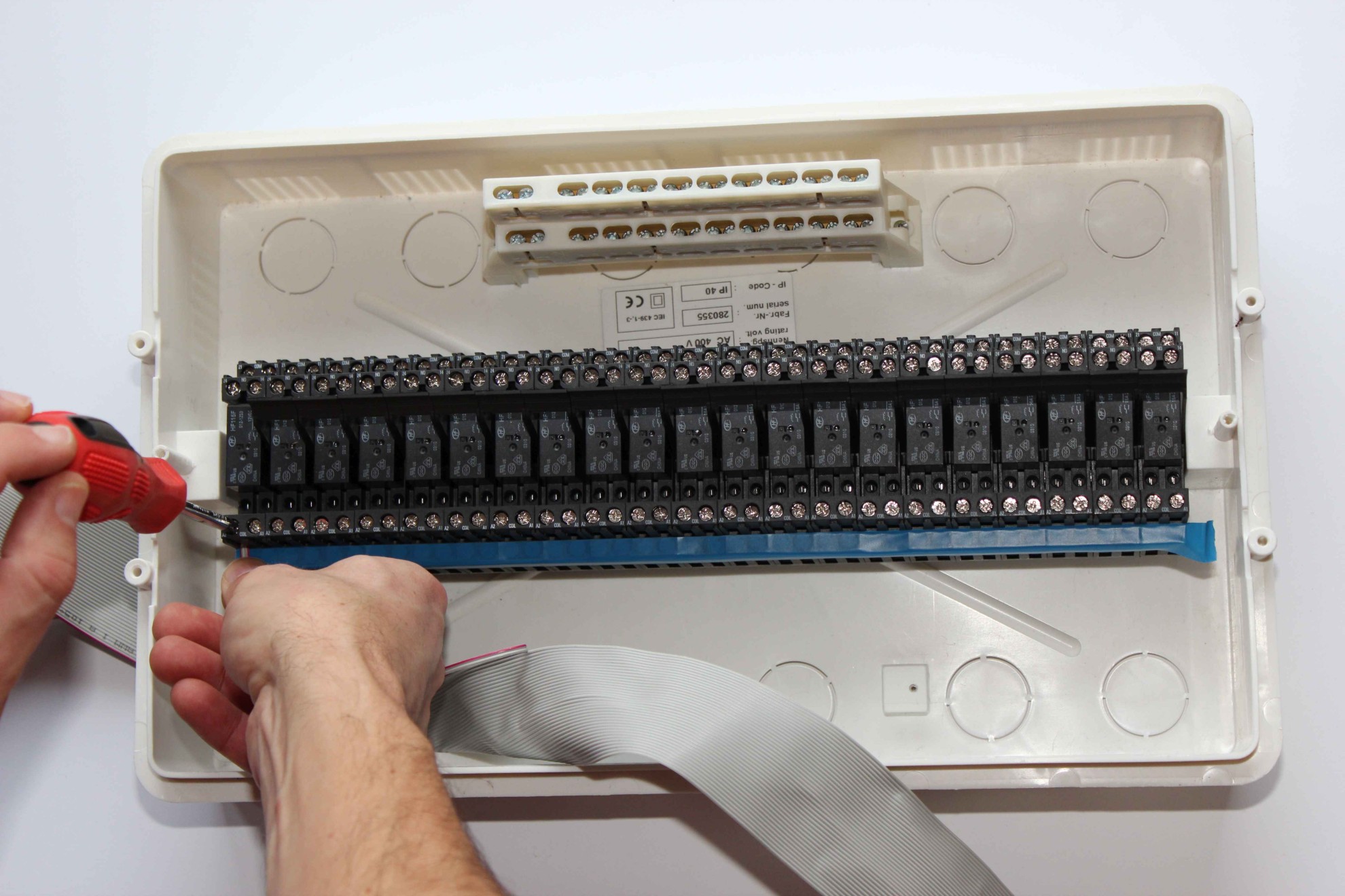
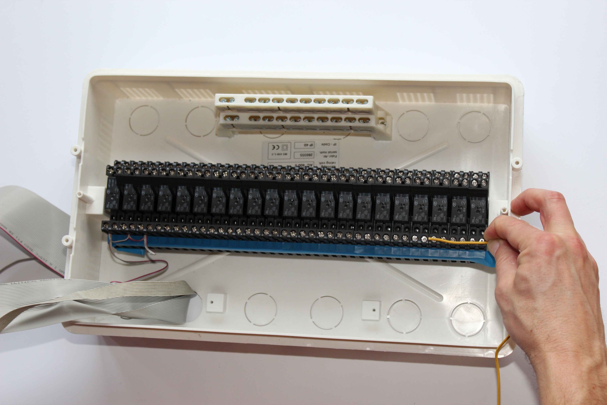
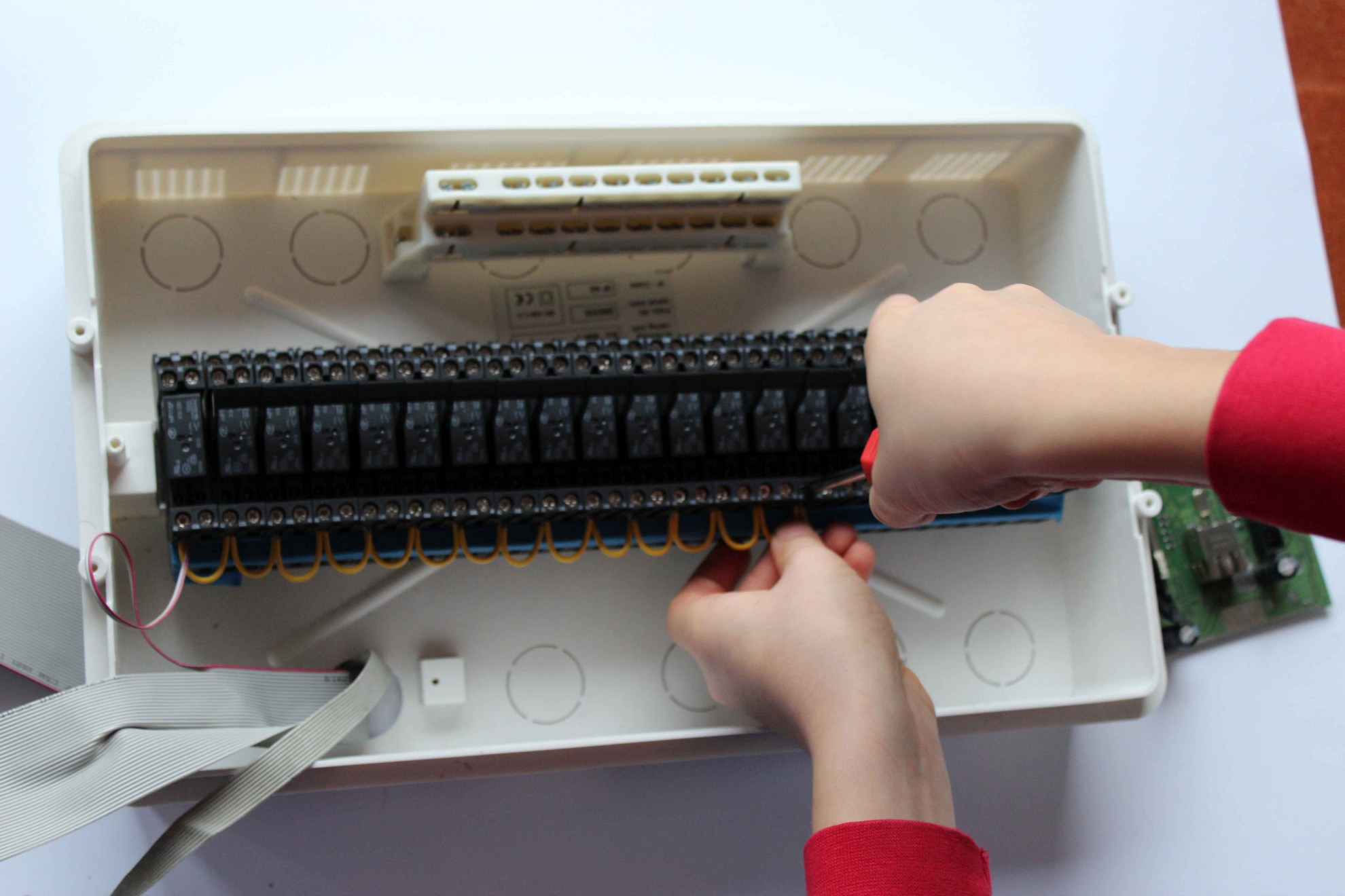
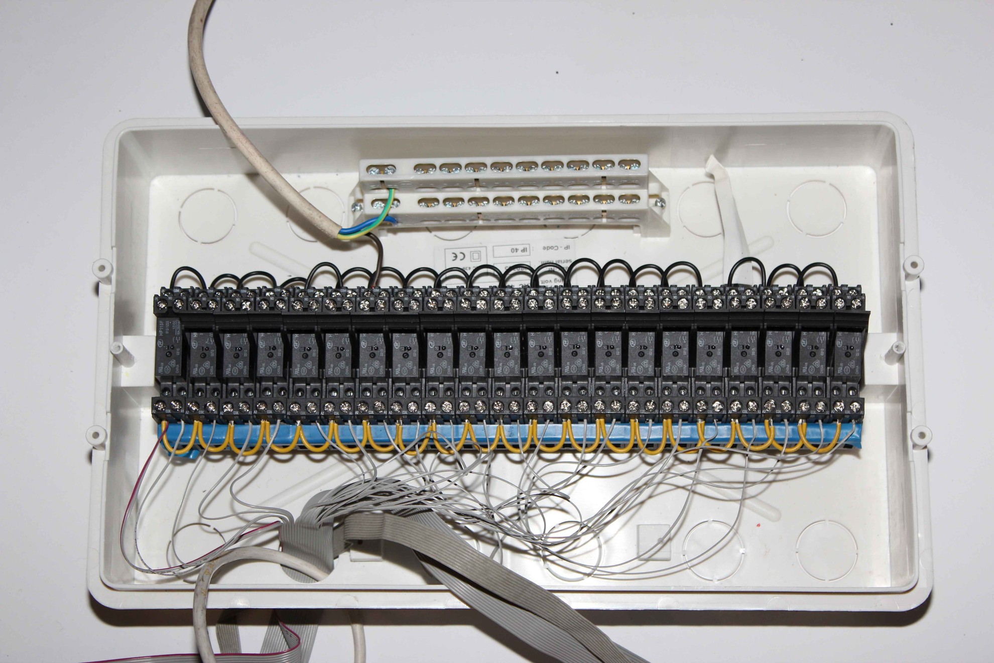
Relays with sockets mounted on the rail all in the same direction, Top-down winding of the coil. You can use the ejector or not, depending on your preference. In the absence of ejector undermine screwdriver is required to replace the relay , but ejectors typically extend beyond the face of relays.
The best way prior to assembly of the complete switchgear to try one relay if it suits: with ejector or without the assembled housing , and check removing the relay. It should also be noted, relays after years can go harder.
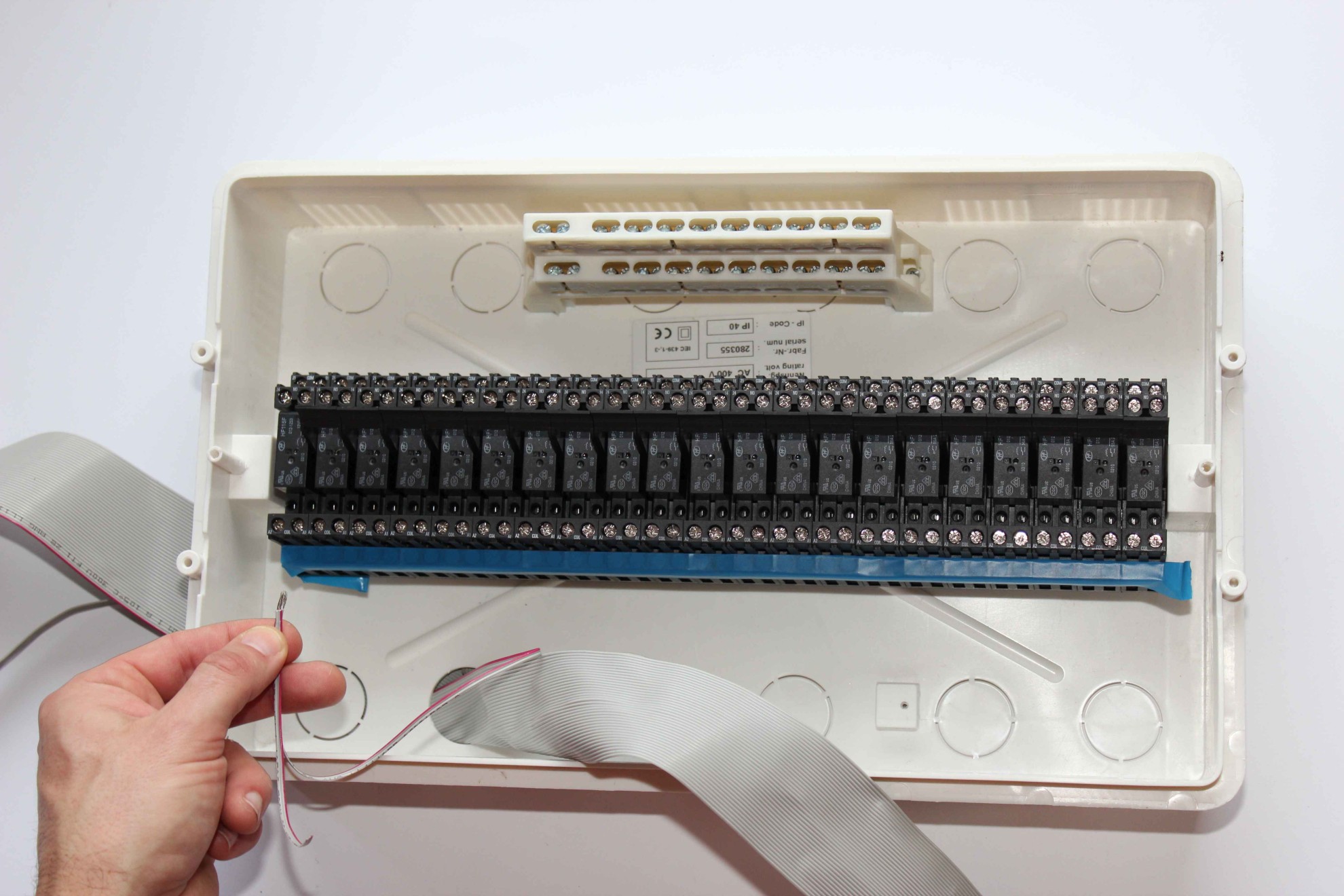
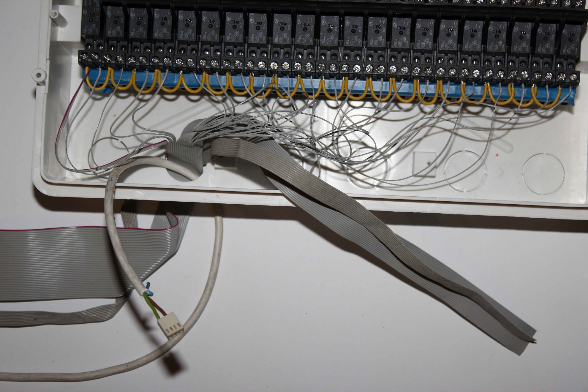
Flat 50/40 pins Tape go into the box so it is not exposed to damage, abrasions (preferably in heat shrink tubing) and will cut the supply of about 20cm to the most far relays to allow the manipulation of the cable and possibly undoing all over the DIN rail.
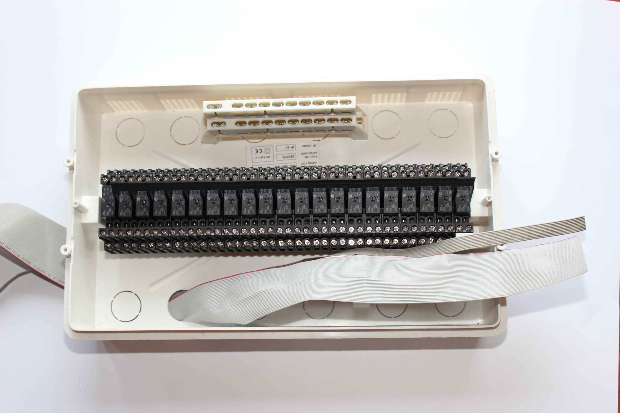
For convenience, you can use IDC-50/40 sockets and cut the wires in the box, if you intend to remove the relays for wet works in the building. It will also allow for the implementation of mini-switchboard on “desk”, which takes far less time and is better and more accurate method. Older RM has IDC-40 sockets newer uses IDC-50 together with power supply.
After the controller at the end of the cable is clamped IDC-50/40 sockets allows fast assembly and disassembly .
External power cable is necessary to connect an external power cord (0, + 12V).
The advantages of installing RoomManager mini switchboard :
- simplified installation – no additional power cable to the controller
- Connecting relays flat belt inside relay box
- Reduced risk of damage to cables ( flat cable ) in the walls under plaster
- slightly cheaper , simpler and faster installation .
Cons of Installation RoomManager mini switchboard
- The need to put out the receiver and IR emitter driver if you intend to use it , unless you intend to install a mini switchboard on top of the ceiling in front of the HiFi equipment which may pose a certain problem.
- Cables to the receiver and IR transmitter may not exceed 8 meters which imposes the place of installation mini substation on the opposite wall to HiFi equipment , TV , SAT .
- Increased cable length to limit the range of the infrared transmitting infrared .
- Very carefully route the wiring in the box , that could short-circuit low voltage controllers with external voltages in this example 230V .
Applying voltage to 12V relays can be supplied together for controller and relays. However, the use of a separate power cord for the relays can significantly reduce disturbances and surges in the system which in extreme cases can increase the measurement errors of some analog sensors ( eg. temperature). In addition, it is possible to maintain power regardless of the relay drivers, which in most cases do not need.
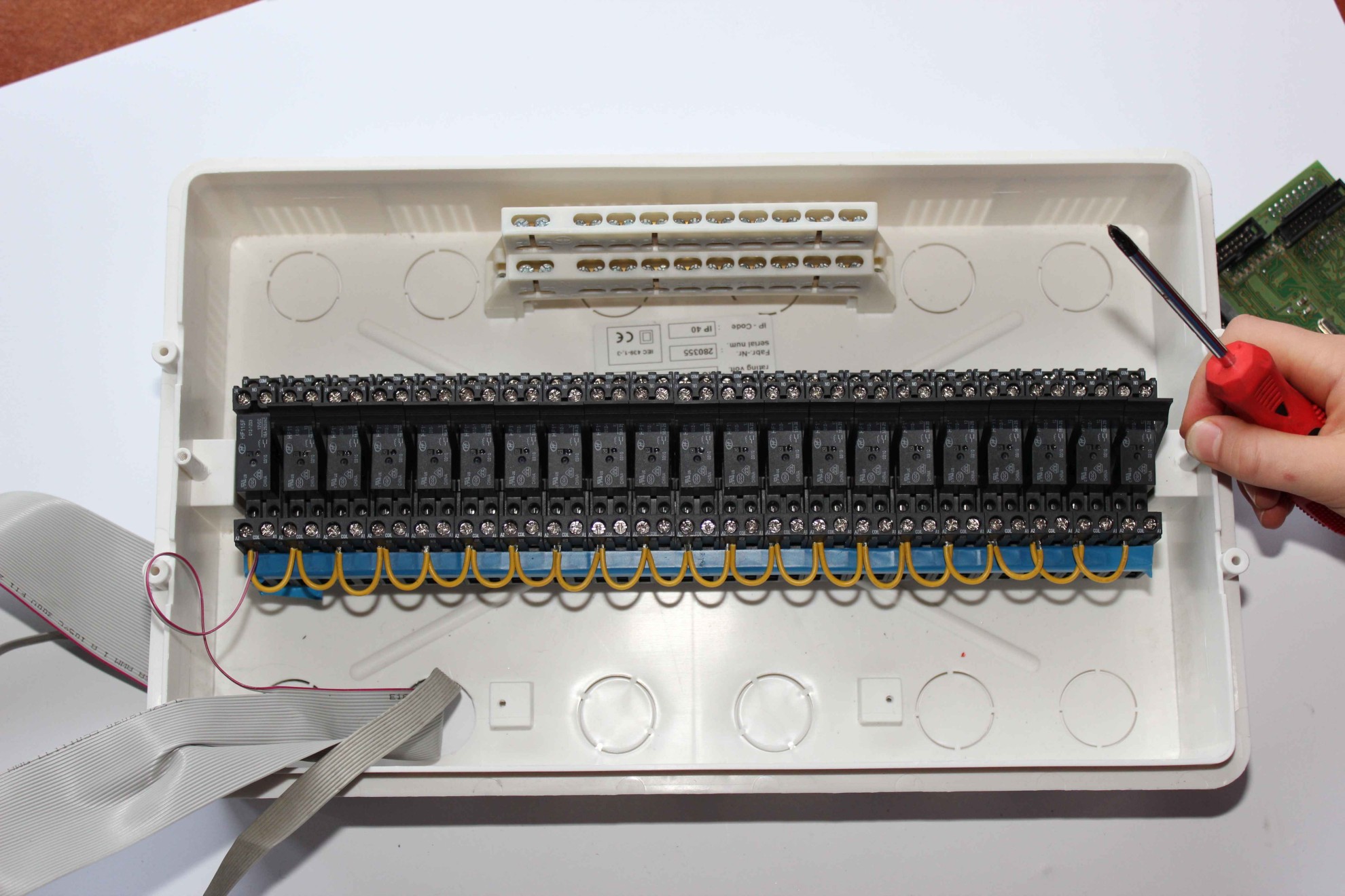
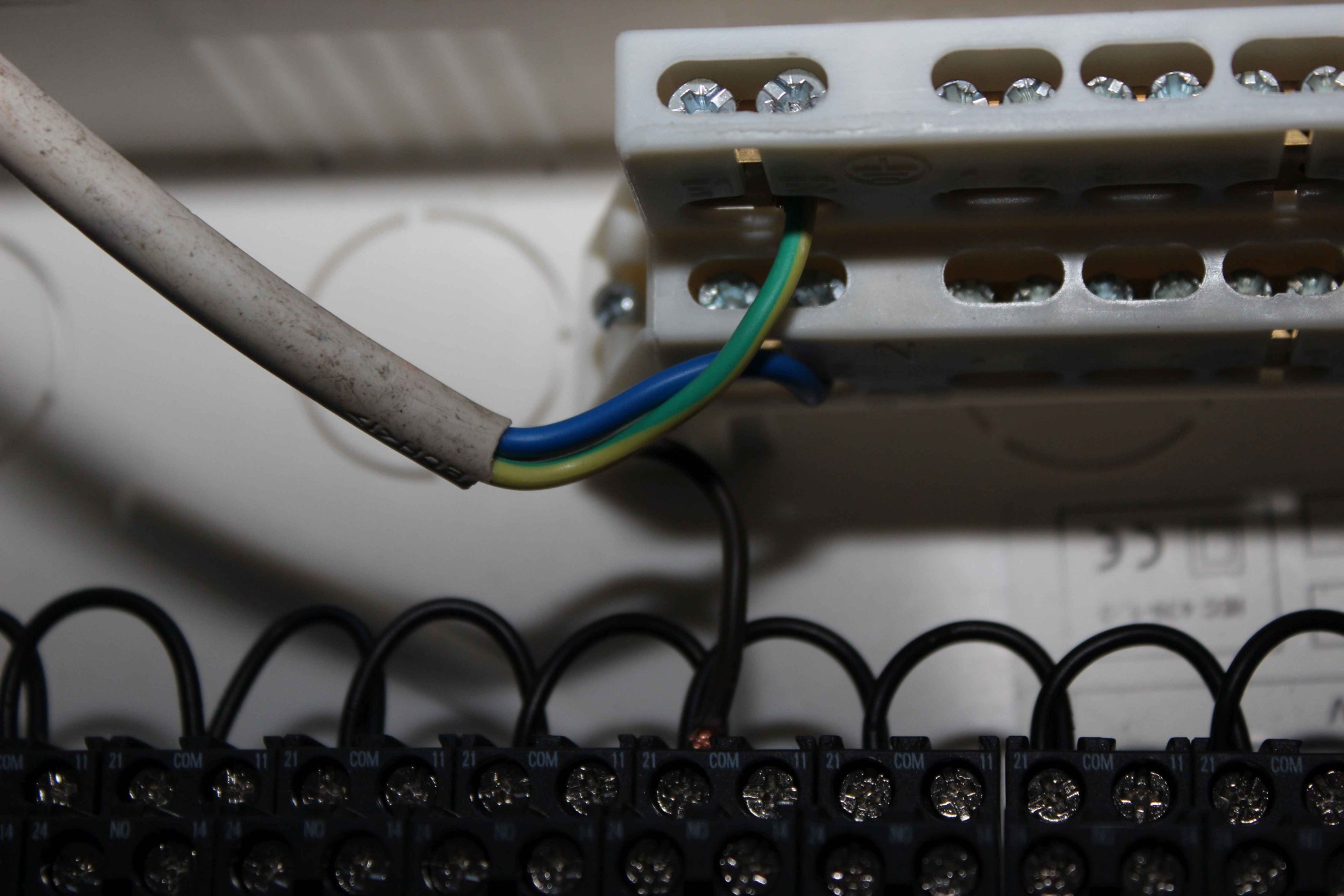
Before connecting cables to the relay must be insulated all the screws below the coil terminals because if the wrong screw wires to the control coils , they may be sliding , short the output to 230V which would cause permanent damage to the controller or whole system.
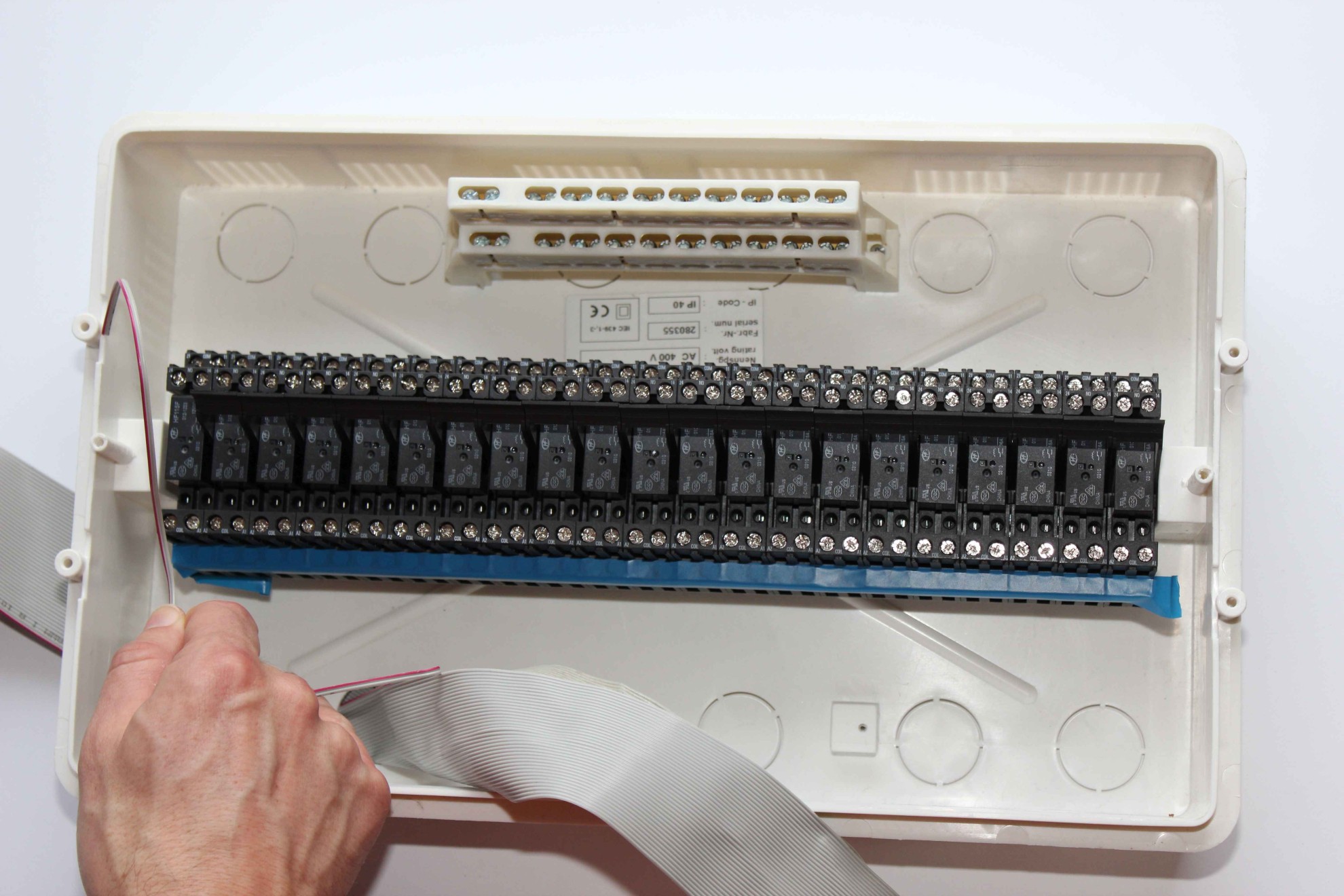
The first cable from the tape IDC – 50 pin is marked red .
The first two wires are connected to a common terminal of each coil . They provide protection against overvoltage pulses generated in the coils .
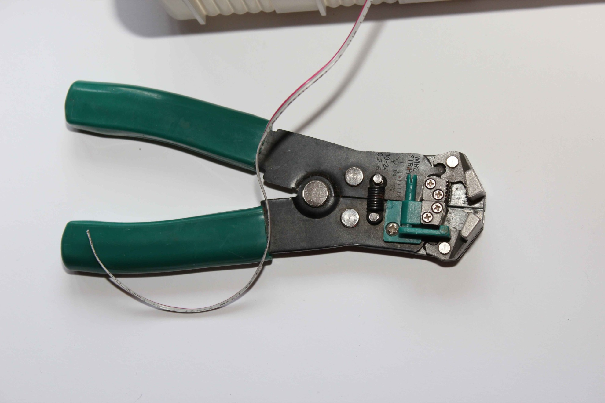
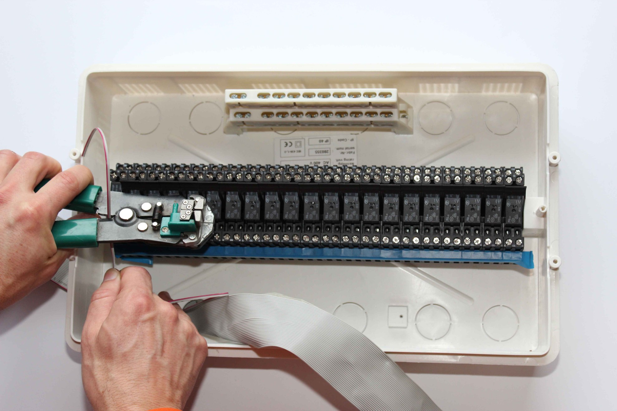
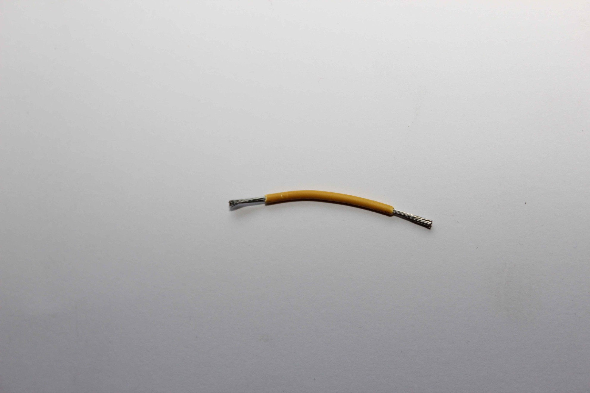
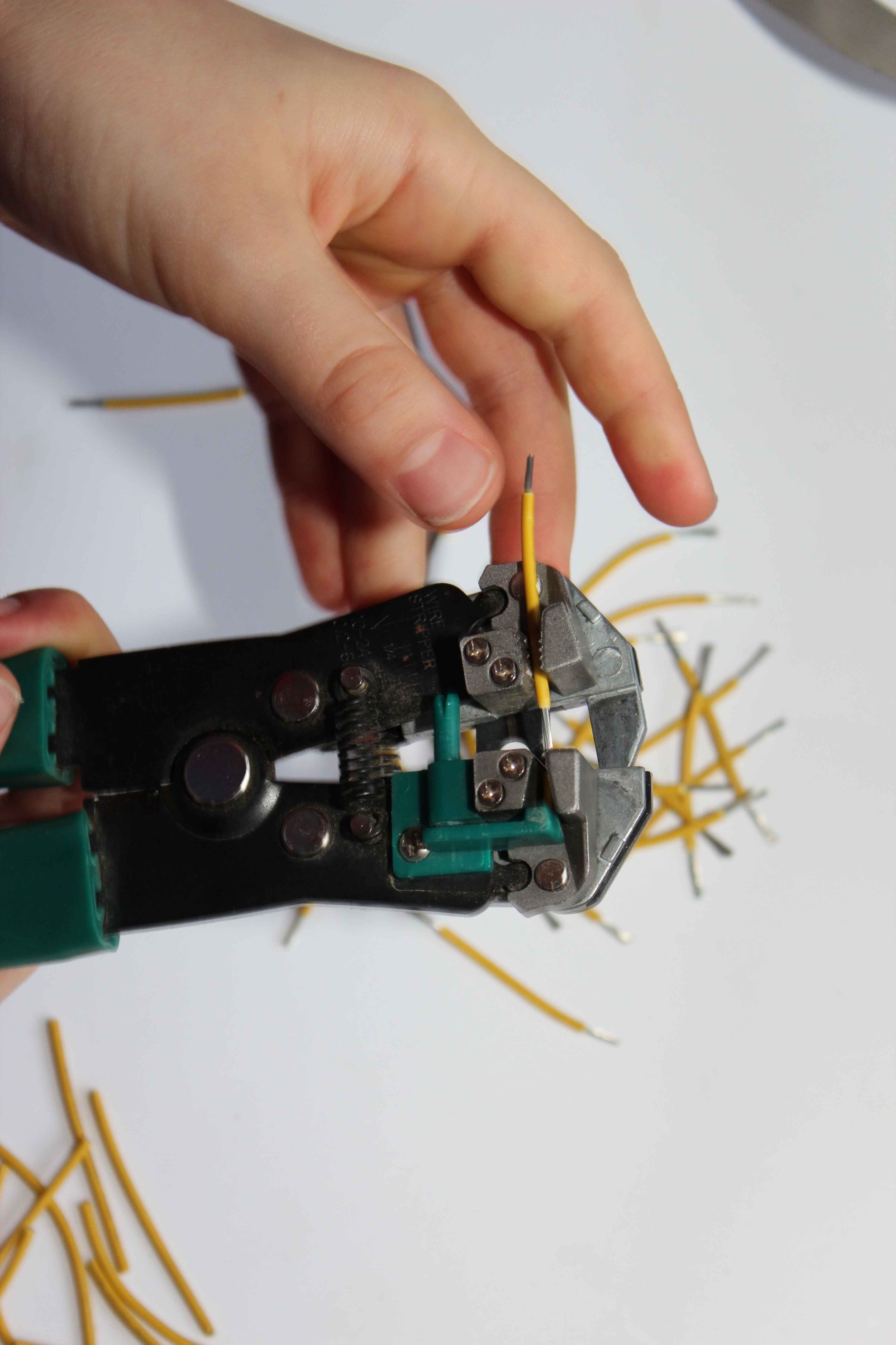
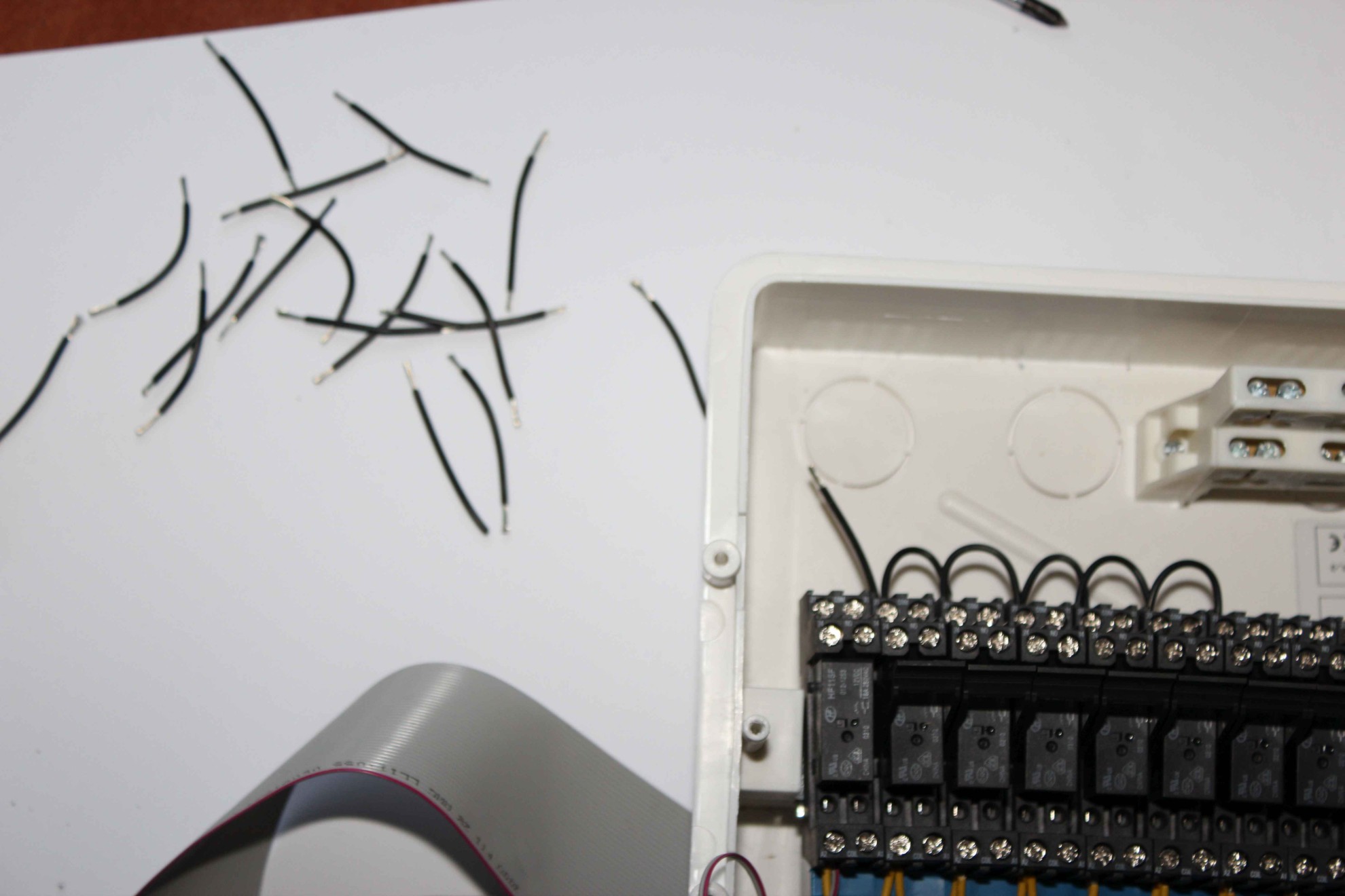
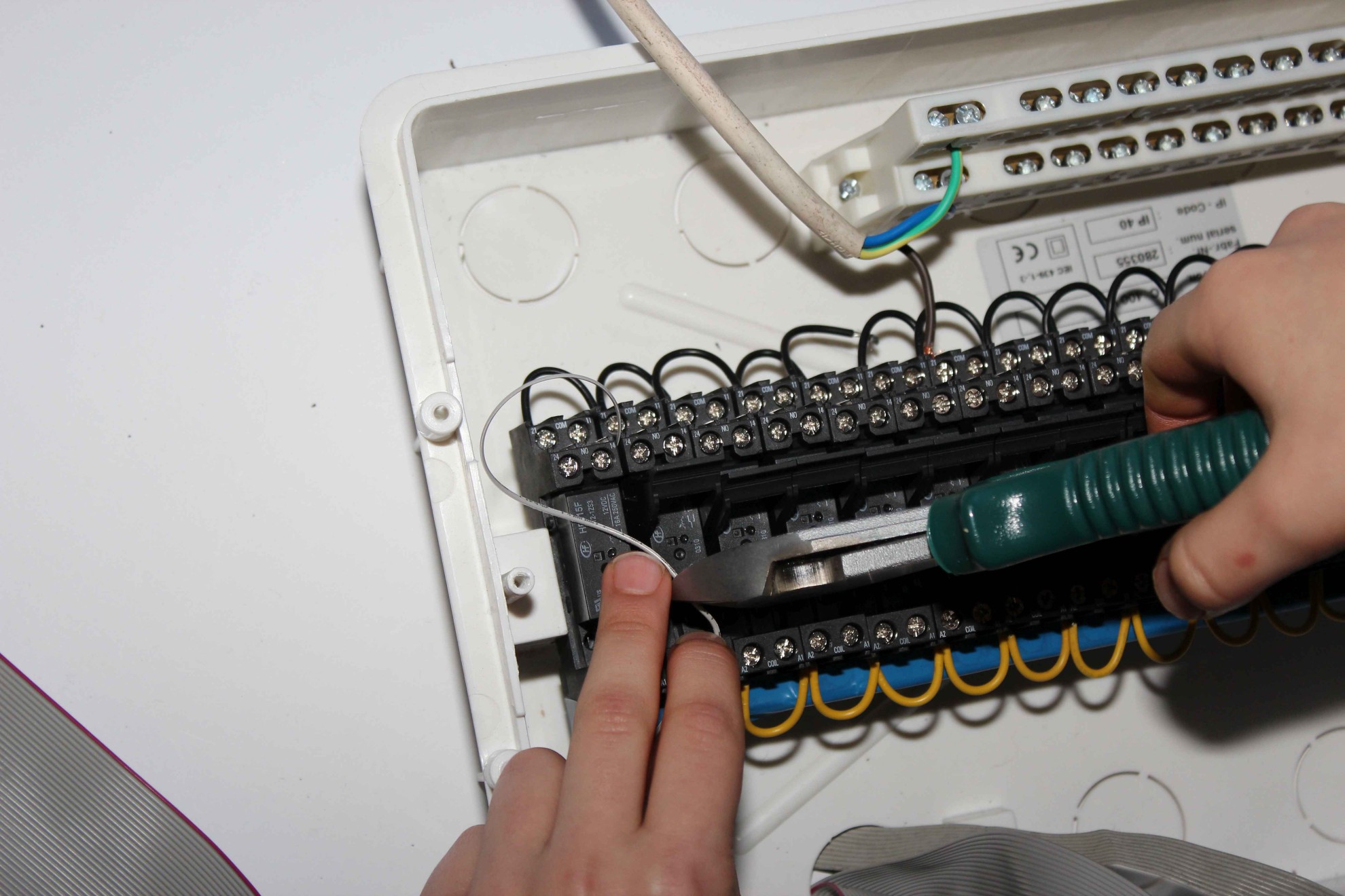
Wires are cut individually to the required length using a tool to isolate .
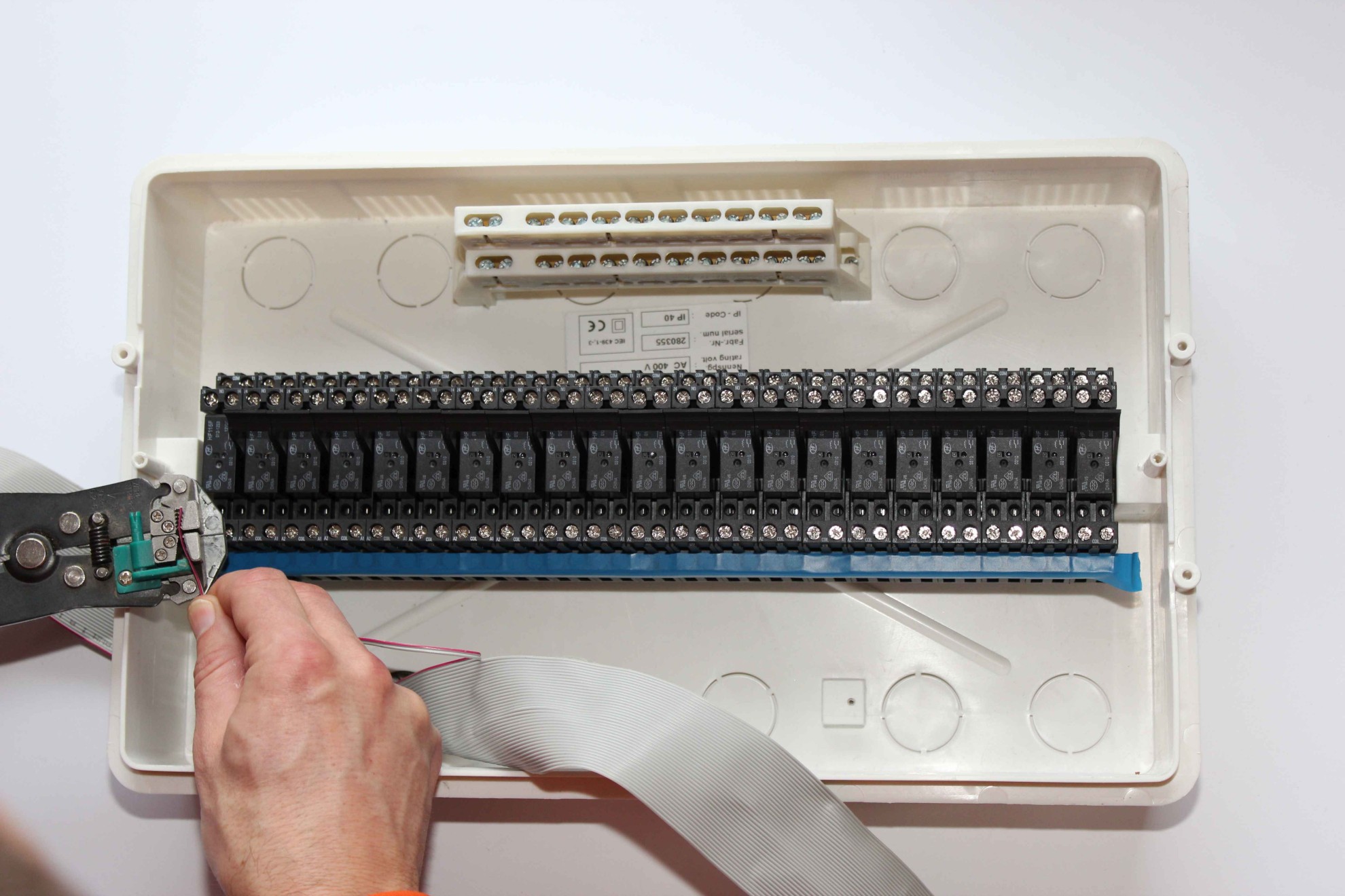
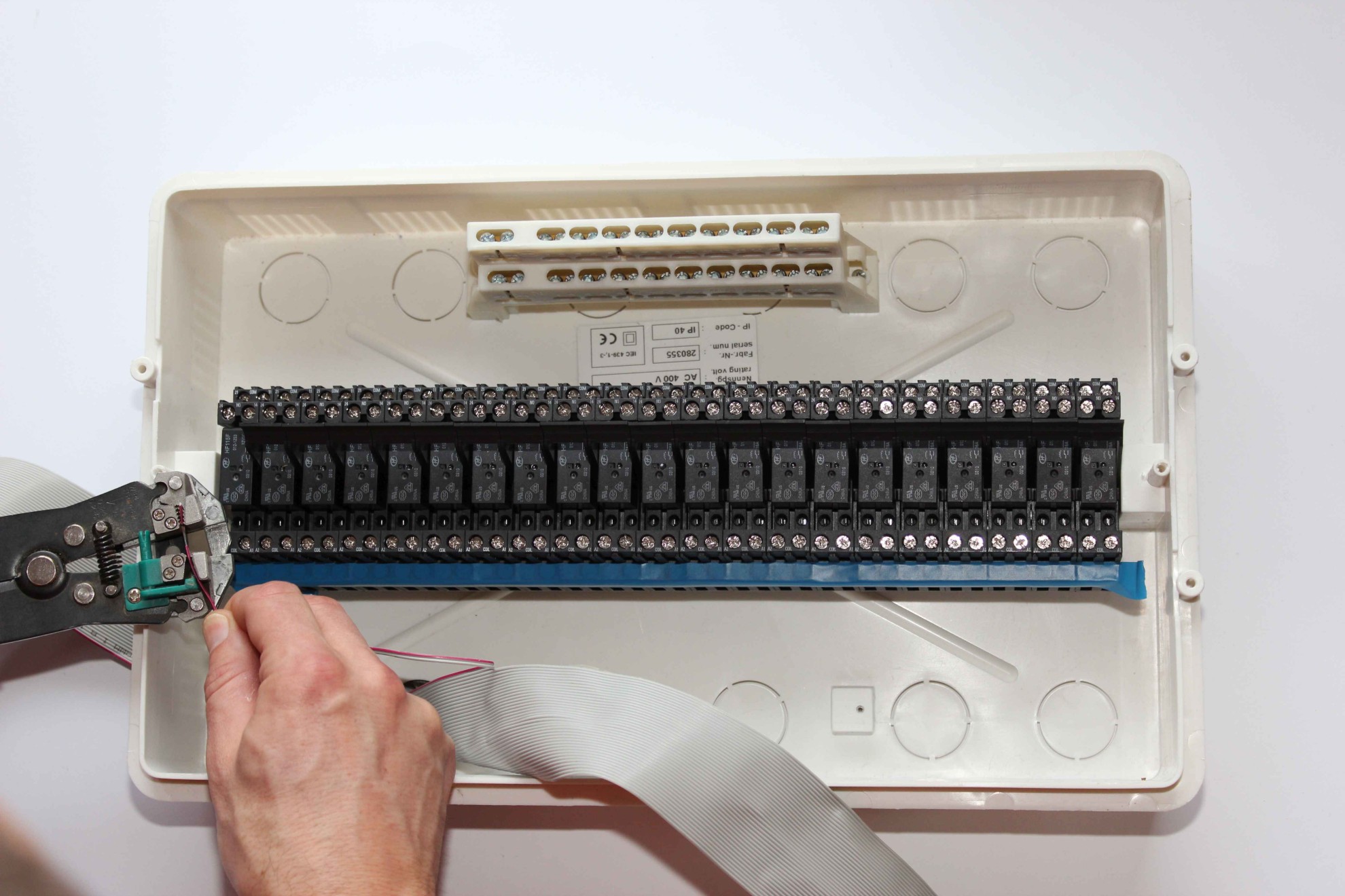
Measure out cable to connect the power supply of all relays .
Isolation of both ends a length of about 5 mm (so that the stripped wire screwed into the connector does not protrude from the relay )
Repeat these steps for all the wires .

Shorts one side of the coil winding ( COIL terminal A2) all relays and protection suppression, cable min 0.5mm2 .
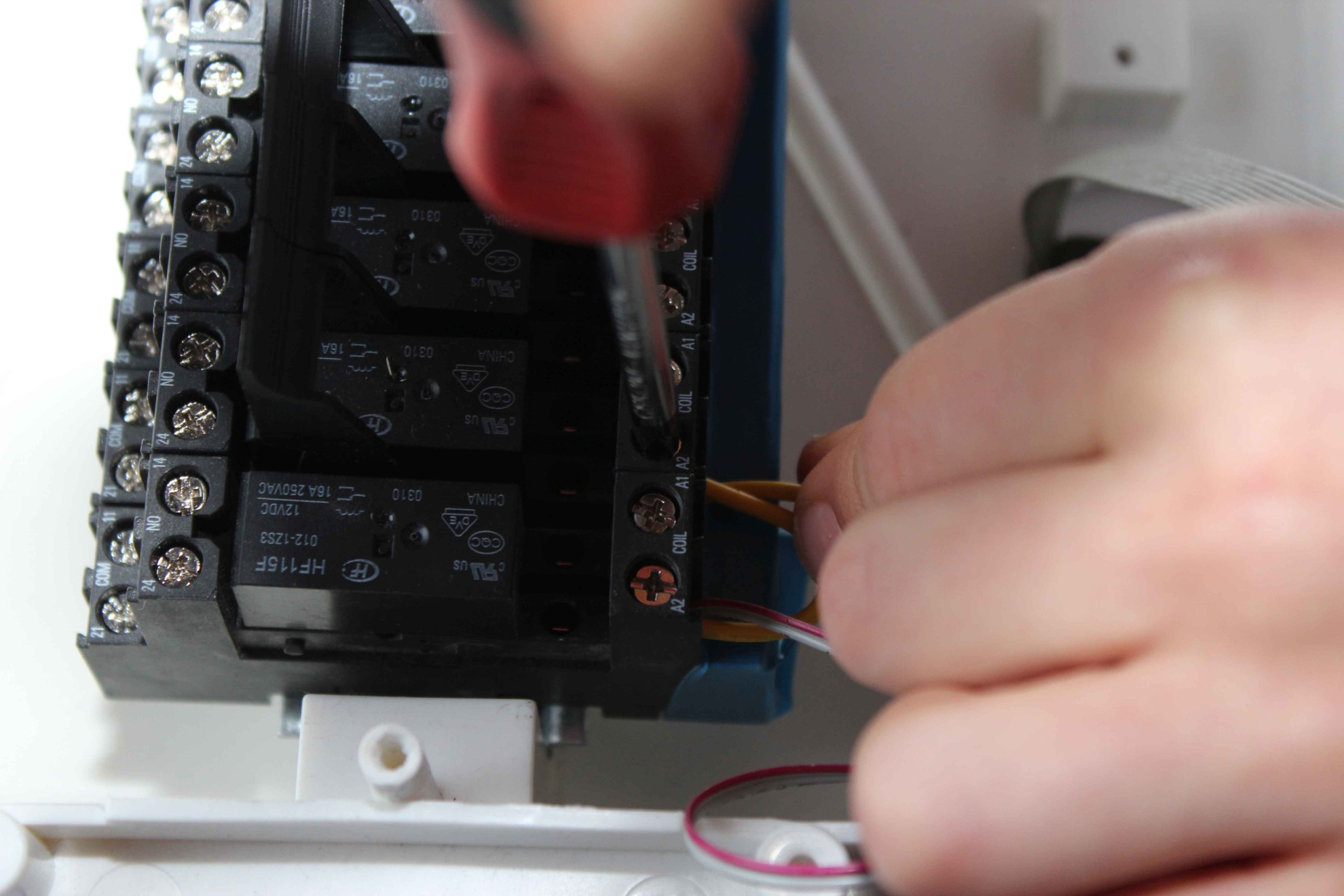
When screwing wires, push them so that bare wires do not protrude beyond the relay and do not endanger shorting to other wires . Be aware of the possibility of entry of insects, worms , rodents, which may short circuit or move wires .
Similarly prepare sections of the minutes 2.5mm2 – circuit the relay contacts added the device to one voltage such as 230V (with one common phase) (COM terminals of the relay contacts) .
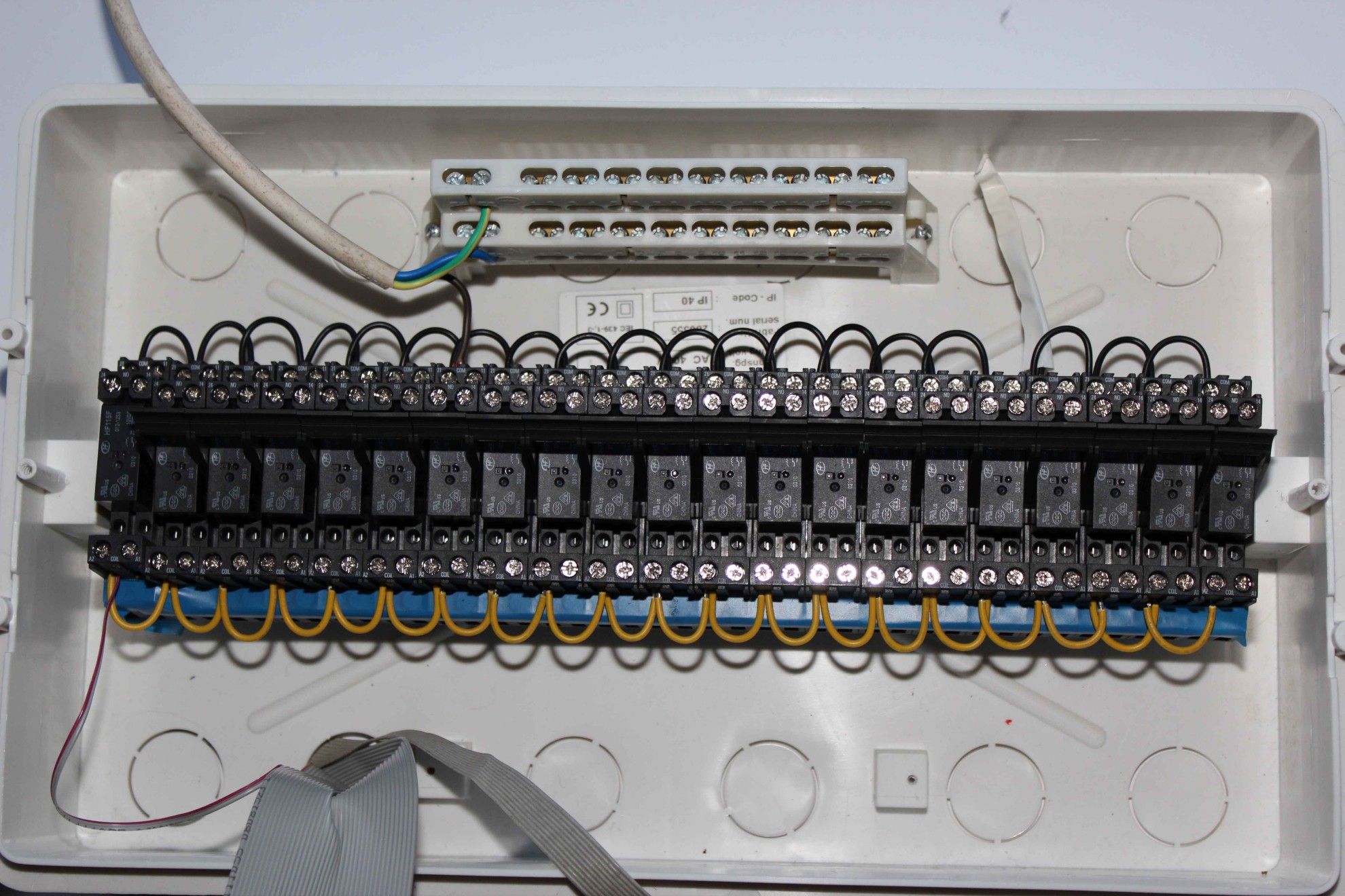
Voltage ( phase ) is connected through a fuse – wire black (brown) for compact relay contacts. Protective conductor (yellow – green) and Neutral (blue) are connected to the rails, which leads to the corresponding wires from the power consumers, sockets, etc. .
While we do not use an excessive burden connection to the distribution should be carried 3*2.5mm2 .
as described in the post
Then connect the outputs of the controller ( the wires with tape IDC – 50 from No..3 { output no. 1} above) .
We cut the wires individually tailored , isolate them and screwed into the second coil terminals (terminal – COIL A1) each relay, to an isolated part of the cable does not protrude from the relay.
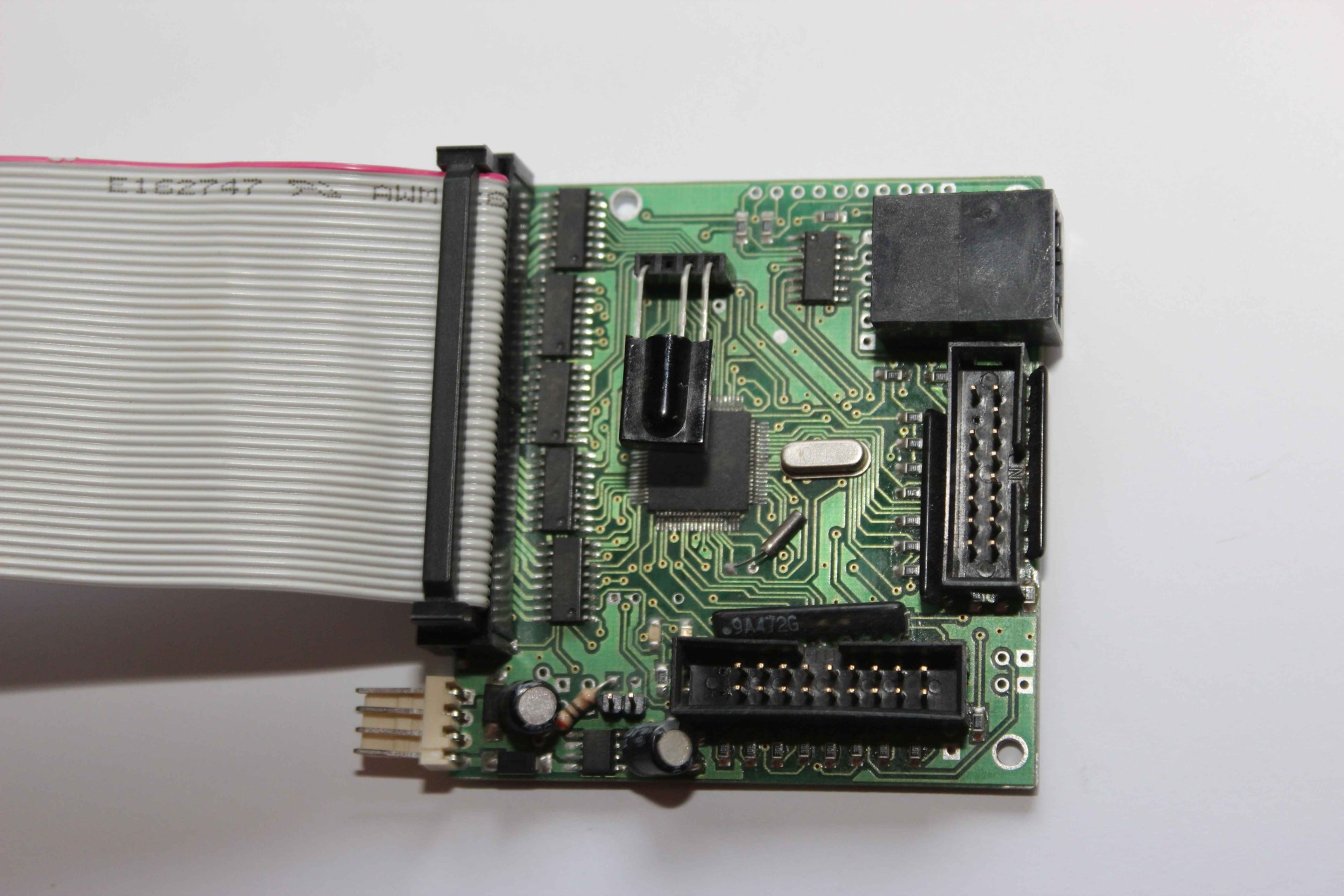
Connecting the power supply to the controller 50 pin flat strip .
On flat IDC-50/40 tape has been derived power cables for the controller:
- pins 49, 50 – VCC 6..+12V . Top with a sustained tension
- pins 38..48 – GND (0V) Ground Controller
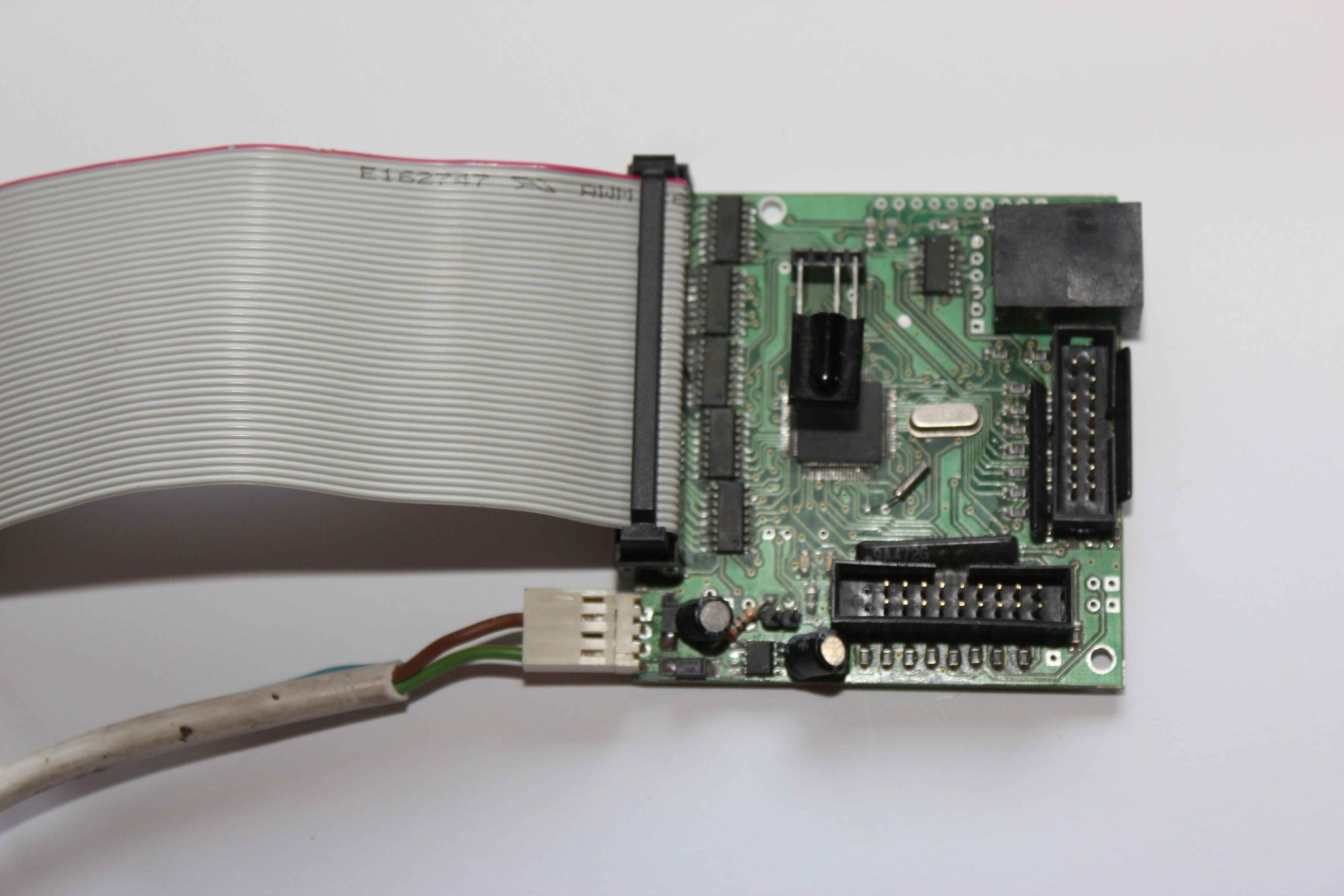
For distances greater than 1 meter must also pull the ground wire between the controller and power supply . Connecting the power supply cable to the controller independent . For longer than 1 meter , or if you do not want to supply the driver with IDC cable – 50 need to connect 2 – external wire power cable ( 1mm2 ) .
Brown wire is connected to ground (0V) power supply (preferably with battery voltage) and yellow – green to a voltage in the range between (+6V..+12V).
If the wires are not fully insulated after work best for the safety of a thick layer of varnish paint or other substances that insulate wire and protect against accidental short circuits .
The remaining wires should absolutely be insulated and protected from traffic and the possibility of short circuits with other voltages .
The same applies to screws coils and low voltage components .
After insulate screws , we can connect appliances cables to the free relay contacts .
Intelligent Ethernet Home eHouse
a description of the driver RoomManager.