eHouse One Electronic House – single segment of Decentralized Installation Diagram – distributed home automation
Smart Home , intelligent Building eHouse is a system of electronic home , optimized for the installation of decentralized ( distributed ) .
Thanks to architecture based on room controllers, allowing , among other things :
- lighting Control
- heating control
- audio-video controls
- smart home
It is possible to achieve savings of the order of 20 times, in relation to other professional building automation systems, based on architecture, built of small intelligent modems ( “small, single blocks” ).
Using eHouse Home Automation system in comfort installation , and most of the resources for a single room RoomManager we earn a lot having lot of spare resources for eventual update in the future.
Further savings can be achieved using plant Home Automation , Building Automation decentralized – distributed , placing the actuators (relays) directly in controlled room, and not in one switching. This allows 230V cable length limitation about few times, which constitute a large percentage of each electrical installation of centralized home automation system. This entails the multiple and proportional reduction of expenditures on work, when laying 230V cables and other high-power.
Implementation of Decentralized Installation requires adherence to the basic rules of the installation of electronic, home automation, distributed control systems, to ensure the correct, trouble-free and stable operation.
This is discussed in the post :
Smart Home , electronic House – Installation of decentralized Do it yourself.
In addition to these requirements , each eHouse segment installation – intelligent Building electronic home , is subject to the same rules .
Installation diagram of one segment of eHouse electronic home ( controller + set of relays + accessory) is shown below .
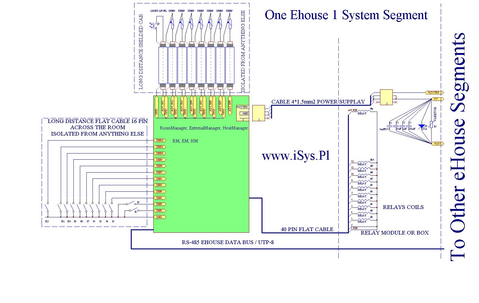 Installation diagram of smart home , electronic building eHouse 1 segment – Zoom Description of scheme:
A single installation of home automation segment connects to the ( electrically) at only one point with :
- power supply (+12V UPS) to power the microprocessor controller
- supply voltage relay ( coil ) (+12V) without sustaining voltage
- voltage (0V) common ground electronics
- eHouse data bus (RS-485) – UTP-8 cable
As conduits for connecting power supply voltage segments, use the cable with a diameter of at least 2.5mm2, three wire (preferably not a wire rope), because globally relays fairly high current draw – 1A, diagonal greater power cables significantly reduce the voltage drop on supply and ground lines.
Between the relay box and the controller cable is best to use 3 or 4 * 1.5mm2 allocating a single cable for power (+12V UPS) and the other shorting to “strengthen” ground of the system (mainly relays) .
Coils combined with RoomManager , 40 pin flat ribbon as shown in the diagram .
Pins 1 and 2 of IDC-40/50 tape are connected to clamping diodes and drivers for relays must be connected to a common voltage (+12V) – relays power.
Driver contains the drivers output the second pole of the coil to ground.
Diodes contain the induced voltage in the coil due to the switching, to the supply voltage coil (+12V) protecting the output drivers and reducing high – voltage glitches . This greatly improves the life of the controllers especially when frequent switching of the coil .
Other pin flat cable 40 pin combined with successive windings of coils and require separation using relays for DIN rail mounting .
In the case of the relay module, flat strip on both sides of the connector is terminated with IDC-40/50 and there is no need to consider how to connect the individual pins or signals .
The diagram does not include relay contacts , which are galvanically isolated from the coil and the entire system eHouse and represent virtually an ordinary electric switch , not activated manually , but by the relay coil.
It is critical to ensure complete isolation between controllers and voltages connected to the relay contacts , because these are high voltage devices from outside the system eHouse and relay contacts and are part of the electrical system (230V).
In addition, to minimize the noise generated by the relay coil on the side electronics home automation eHouse , should be used several parallel-connected capacitors with very high capacitance values span from 1mF to about 10nF . This combination will provide filter out all frequency components of the pulse and interference , occurring on the coils of relays and transmitted to the output drivers drivers .
In addition, highly – voltage glitches , may cause the falsification of analog measurements (increasing the instantaneous measurement errors ) , during the switching relays .
Further safeguards against interference and surges generated by coils can be switched high-power diode , switched between ground (0V) a plus voltage relays (+12V) in the reverse direction.
Additional protection against overload may be a varistor connected in parallel relays supply.
In the case of producing a pulse voltage exceeds the voltage of the zener diode , It directs the voltage to the ground.
Another element of the installation of a single segment eHouse home automation is to connect digital inputs . The controller has available IDC-16/14 connector , to connect the flat cable connector with clenched IDC . In analogy to strip all signals RM must be fully isolated from all other .
This is only permitted placement of switches or sensors , the contacts ( without connection to external voltage ) short ground signal (GND) to controller line input (Dinx).
The strap guide the best controlled at about room , at the height of the planned electrical switches (normal or bell -type panels with switches ” push – button ” ) , putting them at critical points in the wall socket and creating a loop for easy clamping coupling .
The tape is placed flat on the wall such as the wall taping , without having to break open fissures before plastering .
It is necessary to ensure that it has not been damaged during cans installation .
The next step in the installation of a single segment of home electronics is connecting analog sensors ( measuring ) .
In the case of the light sensor (phototransistor), and temperature sensors (LM-335) is not necessary to connect the power, because they are powered from low current measurement input via a resistor Pull-up ( from microprocessor controllers with CPU Power 5V ) .
Similarly, This segment must be isolated permanently from any external voltage .
Although the Analog Inputs RoomManager are on the plate with the connector IDC-20 ( for flat cable 20 pin ) , preferably as soon as possible “go” shielded cable, the distribution pipes at a distance greater than 1m.
Is permitted only with sensors connecting them between the grounding line (screen) and a signal wire (middle), no additional power supply or connect.
In situations requiring the use of power for sensor, necessary to select the sensor with a voltage, such as the processor driver eHouse, and energizing it with a voltage regulator controller, if it does not need too much power for operation .
If it is necessary to place sensors on the outside , in a wet basement, etc. you should ensure hermeticity , waterproof and complete electrical isolation of the sensor ( eg multiple lacquering and flooded with epoxy resin ) .