Intelligent Building eHouse.PRO – DIY 2
eHouse.PRO Smart Home | intelligent Building .
A professional building automation system with the possibility of self-assembly: part two assembly description .
Before you read this post please refer to:
Intelligent Building eHouse.PRO DIY
The next step is to connect the module of intelligent outputs to the relay module.
Similarly, as digital inputs connected to them tape IDC-50 for the quickest installation (connecting 50 wires to the relay contacts in seconds instead of hours).
Be careful not to confuse the input tape which would cause damage of eHouse.PRO electronics.
Smart module 128 outputs eHouse.PRO has 4 IDC-50 each containing 32 outputs with drivers for relays compatible with leads of EthernetRoomManager .
Basically any combination of the relay modules MP-12 , MP-18. However, 18 modules enable the most convenient installation in large switchboard .
In eHouse.PRO Modules Relay MP-18 (including 18 relays) and to get all 32 outputs is necessary to use the basic module (IDC-50) and extending ( IDC-20) to operate the last 14 Relay.
Depending on the size ( width of the cabinet ) modules can be installed one above the other (cabinet with a minimum width of 18 modules ) or side by side ( requires rack rail with 36 modules )
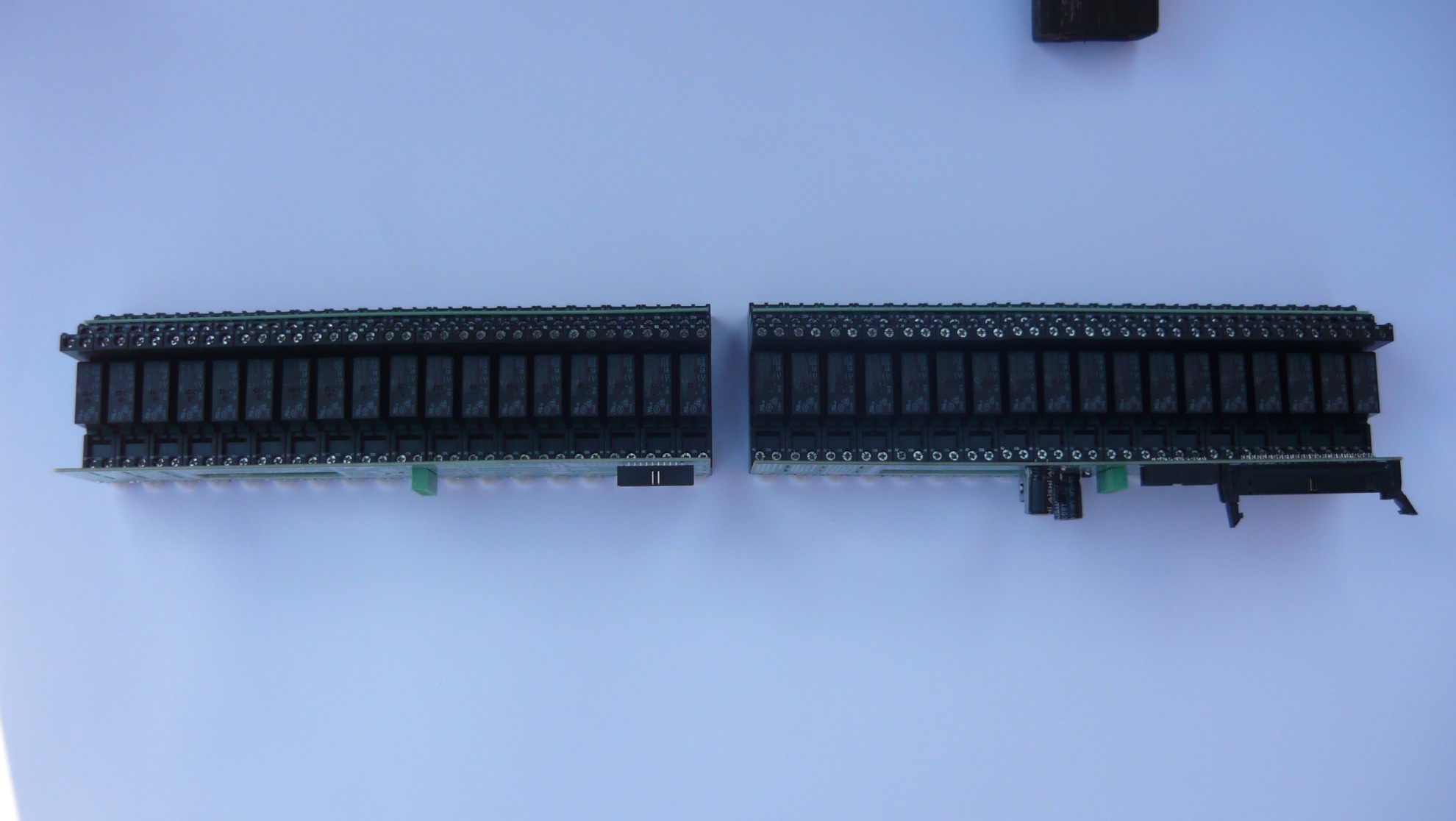
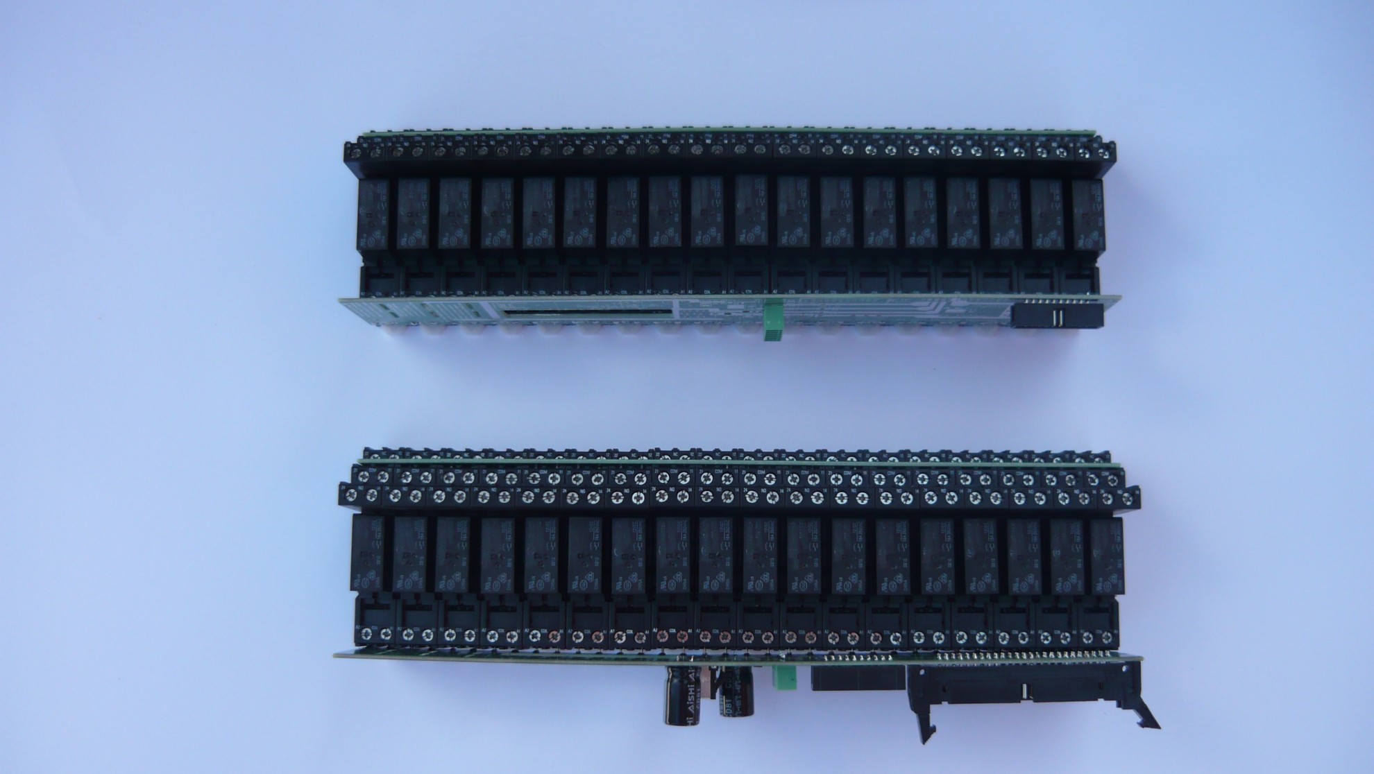
Expansion module with basic flat cable connects to IDC-20 (the length is not critical – up to 3 meters)
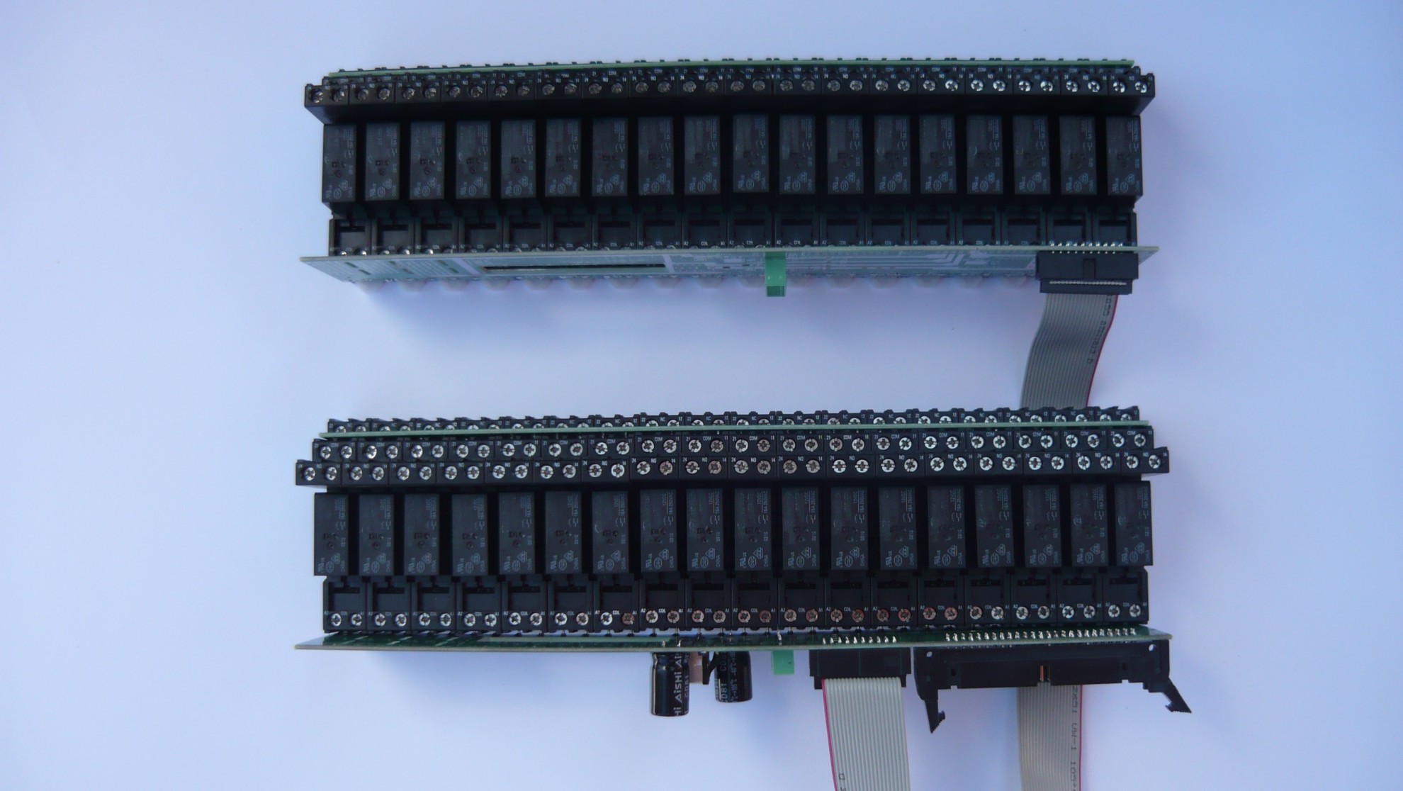
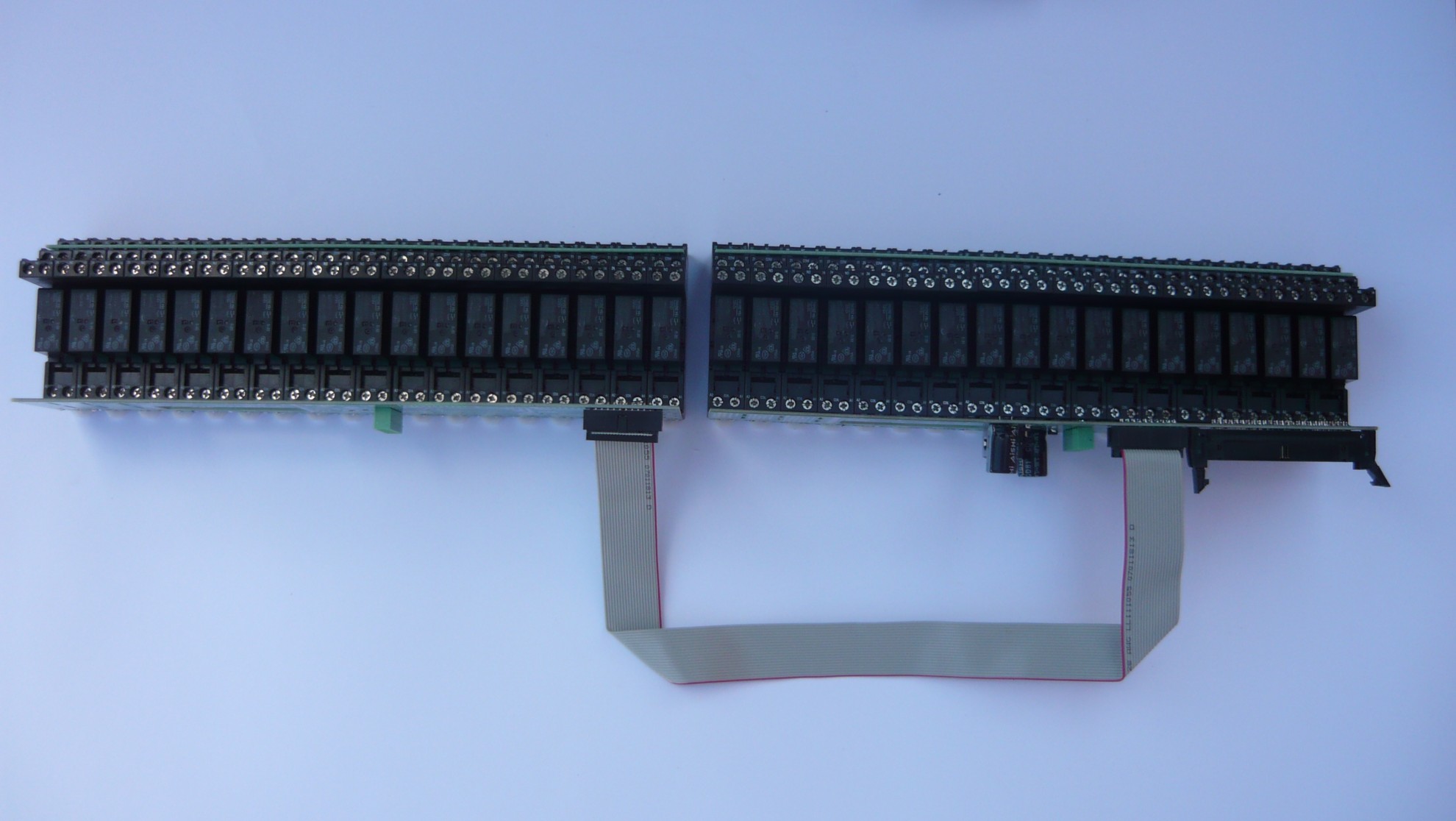
Basic module with relay output module combines intelligent tape IDC-50 (the length is not critical – up to 3 meters )
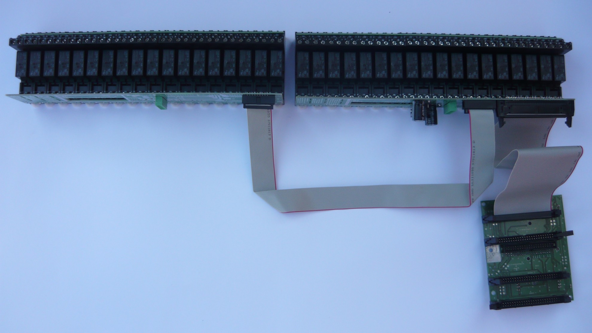
Depending on the demand for the output can connect another relay modules for subsequent IDC-50 on the module of intelligent digital outputs .
The next step is to connect the isolated power supply 230VAC/12VDC/8A on the needs of the entire automation .
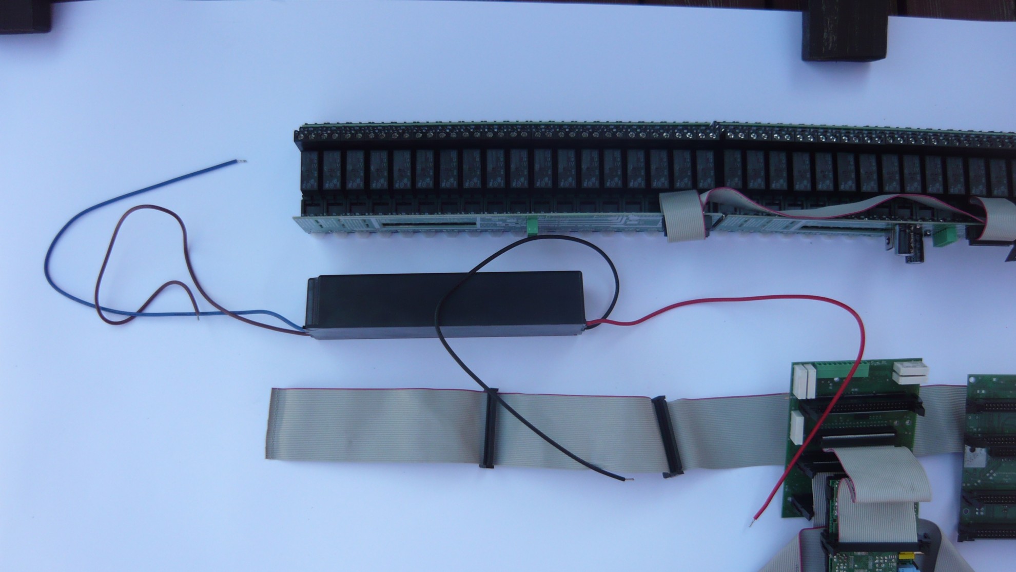
It is used for the green port ( 6 pin ) that requires a single screw adapter cables : 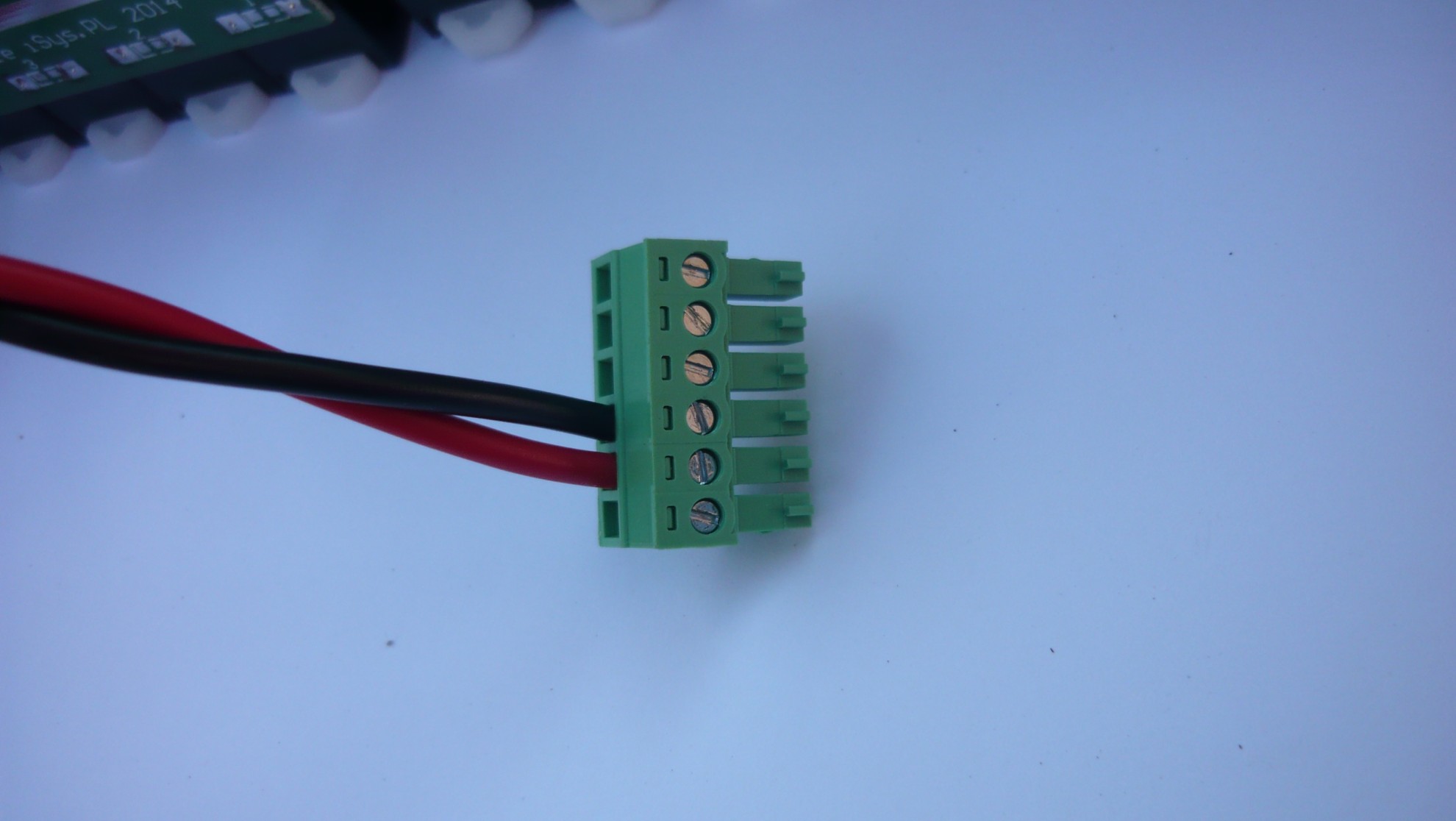
And plugging into one of the basic module MP – 18: 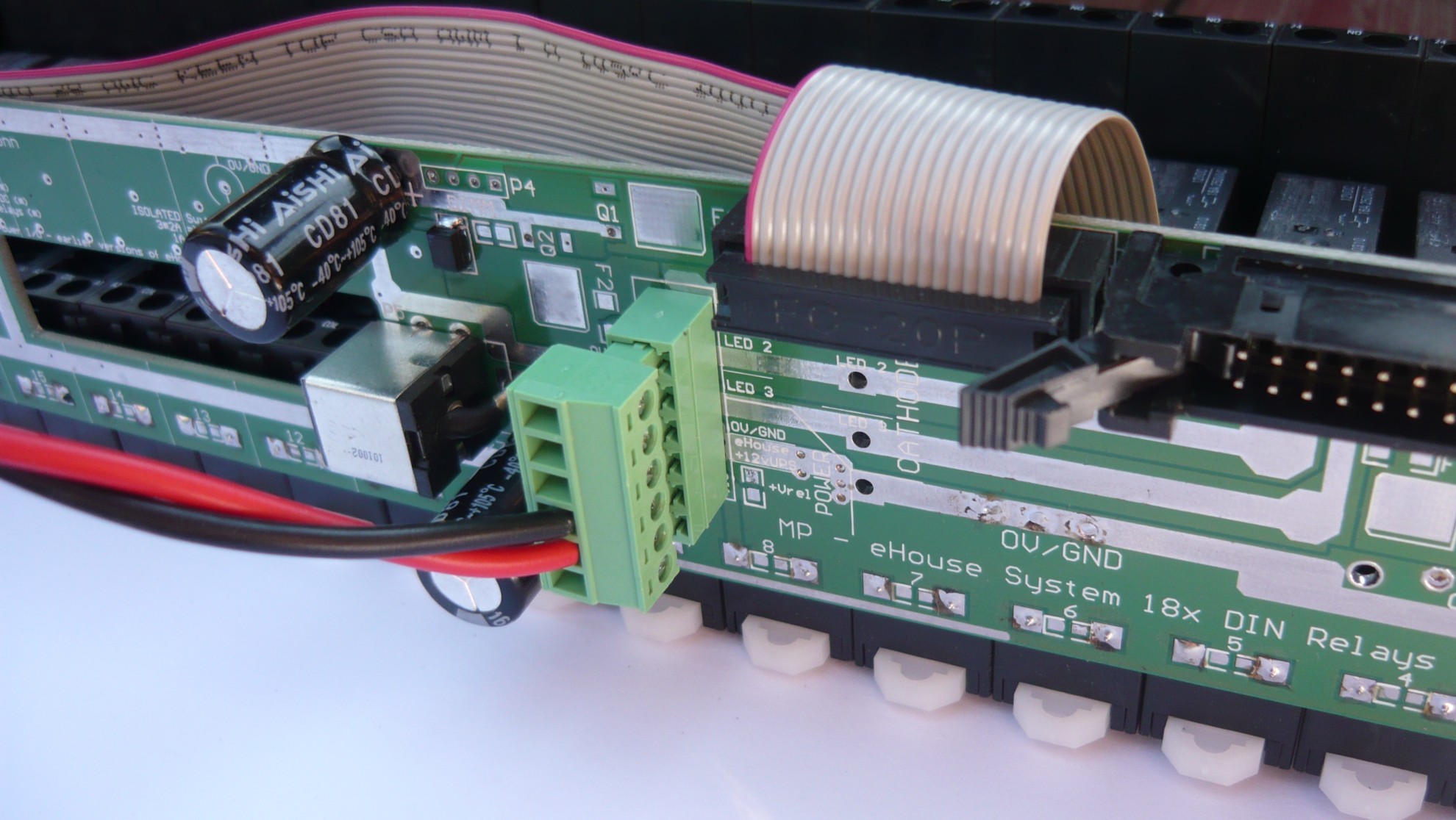
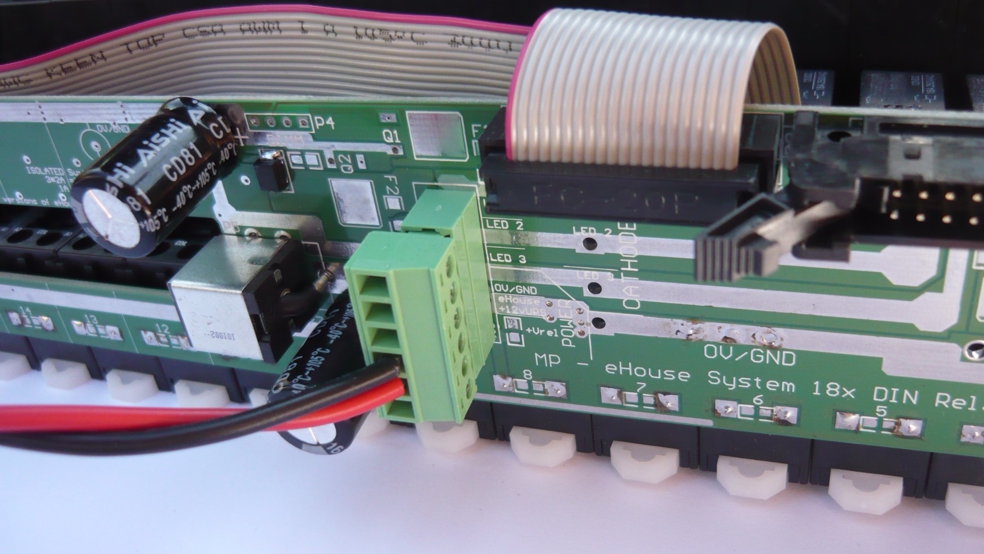
Basically one power cord plugged in only one relay module should be enough.
In the event that we are going to use one voltage relays and electronics (12V) to short pins 5 and 6) .
If you are going to use different voltages , eg. sustained tension for drivers, voltage relays connected to pin 6, and for drivers to pin 5 (ground must be shared).
If, however, use a large number of transmitters may be necessary ” strengthening of ground and power plus relays” (all pins 4 – ground 0v ) and (all pins 6 – voltage relays).
The other side of the power supply must be connected to 230V after checking the entire low voltage installation.
The relays have a standard bolted connections for direct screw 230V wires.
Common relay contacts (COM ) can be shorted with rail, if you are using a common voltage for all devices (including the same phase).
Buy eHouse.PRO : Intelligent Building eHouse.PRO