Connection and testing of eHouse EthernetRoomManager , EthernetHeatManager controllers using the Debug/Evaluation Module
Ethernet Smart home demonstration module allows testing and evaluation of all eHouse LAN smart home controllers.
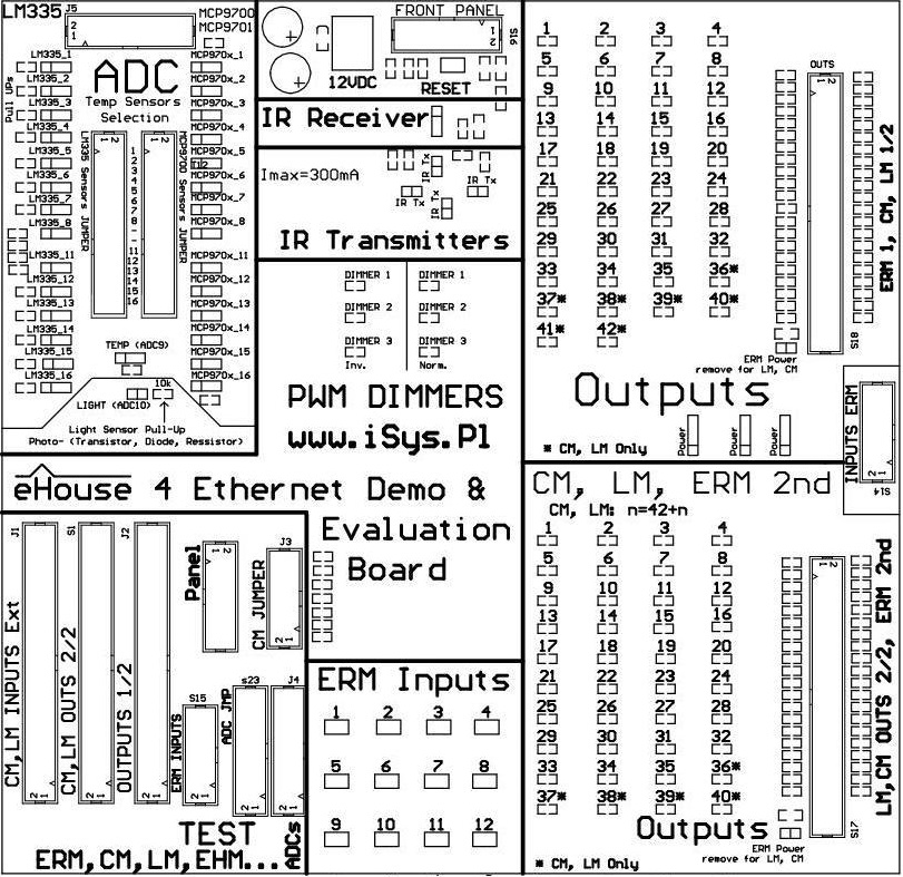
Evaluation Module is eHouse intelligent building have all hardware resources stored on one PCB replacing production facility at home. Connecting the demonstration to the controller is very simple and requires only the connection of relevant “tapes” between the microprocessor controller and the demo board.
Ethernet smart home controllers can be divided into two basic hardware options :
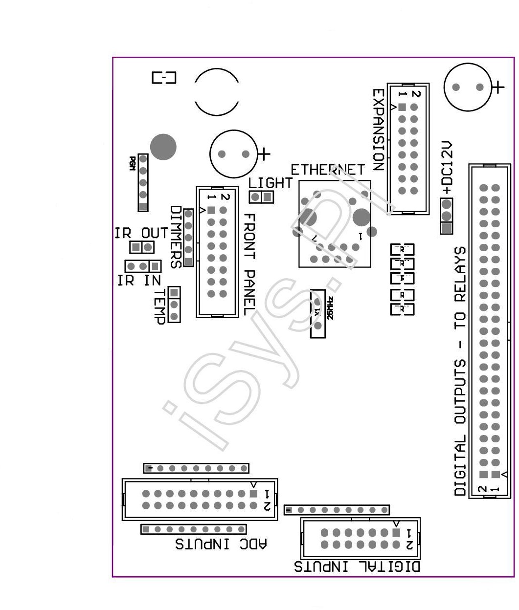
- mid-range controllers – based on EthernetRoomManager PCB
- large-range controllers – based on CommManager / LevelManager PCB
In this post we will discuss testing, education and evaluation ( based on ERM ) using Ehouse4Ethernet DEMO module.
At the beginning, make sure that the power module is disconnected from demo and ERM has removed all cables and connectors.
To fully analyze behavior of eHouse LAN smart home controller must be connected to the following ERM connector between modules DEMO and ERM :
- Remove all cables from the connectors in “TEST” section
- flat tape 50 pin for outputs ( S18 ) . Short the jumper “ERM Power” the connector s18
- flat tape 14 pin for inputs ( S14 ) .
- flat tape 16 pin (S16 ) for external ERM panel ( Infrared , temperature , lighting , dimmers ) .
- flat tape 20 pin ( J5 ) for Analog/digital converters .
The next step is the appropriate combination of sensors connected to the inputs of the A / D converter .
For ERM to be shorted jumper “Light” connecting light sensor to the input of the A/D converter via external panel socket. For other controllers it must be disconnected.
In addition, the sensor are related to the temperature sensor selection jumpers , which in the case of connecting light sensor require removal of jumpers for input 10 on both 32-pin connectors .
If we are dealing with a controller other than ERM and we need to input A/D converter connected temperature sensor MCP970x :
- disconnect the jumper ” Light ”
- disconnect the jumper for input 10 on the connector 32 pin for LM335
- short the jumper for input 10 on the connector 32 pin for MCP970x
The next step is for configuration the remaining temperature sensors, connecting them to the required inputs.
They are used for the 2 x 32 pin, allowing the individual connection of LM335 or MCP970x sensors to any measurement input.
You can select only one sensor type.
Activation of the LM335 sensor also provides connecting a resistor (pull Up ) to +3.3V which provides power to temp sensor.
This is a much more secure connection of the sensor than full-powered sensor, because short pin sensor does not cause a short-circuit power supply of controller.
LM335 Sensors , however, in the case of Ethernet controllers do not have a full scale measurement, and measure the temperature to about 56 degrees C. In the case of very low temperatures may also be the effect of the thermometer by self heating itself too much from power current , because these sensors are working optimally for 5V supply voltages .
For example:
To connect the sensor to the input of LM335 No. 7: in 32 -pin connectors remove the jumper in row 7 for MCP970x and short circuit for the LM335.
To connect the sensor to the input MCP970x No. 6: should be in 32 -pin connectors remove the jumper in row 7 for LM335 and short circuit for MCP970x .
Please be aware that depending on the type of controller (kind of PCB hardware and interconnection module) of the inputs can be connected to a printed circuit board . Please refer to the detailed documentation of the controller, that measuring inputs are not physically connected to other resources .
While we do not use the controller, that has all measuring inputs as free as ( EHM , ESM) should reduce the input connections that are right for each medium controller -> free (3 , 5 , 6 , 7 , 8) .
The next step is to connect the Ethernet controller to the Router or Switch with a LAN RJ-45 standard cable.
After checking and verifying that all cables are correctly connected and tightened, 12VDC power supply can be connected to the module board demo which is also the power supply for the controller.
Testing of Digital Outputs
Digital output states are displayed on the LED in ” OUTPUTS ” section on evaluation unit .
LED lights for the corresponding output means its ON and turn on relay in the production installation.
Demonstration module has two independent sections ” OUTPUTS ” which allows simultaneous checking outputs of two independent mid-range controllers ( ERM , EHM , ESM , etc. ) .
This is particularly important if we want to associate the event of one controller to the other controller:
from being sent from the first , and we intend to test.
“ERM Power” jumper assures additional powering mid-range type controller via 50pin flat tape is necessary to short-circuit in each section “OUTPUTS”.
Testing Digital Inputs
The Ethernet controllers digital inputs are connected through resistors “pull Up” to power supply of the controller (3.3V).
To activate them you need to short the input to ground. Due to this, control event for smart home system can come from different sources , mono-stable switches are used (Ring) .
This prevents events collisions when such switch forces input active all the time.
The inputs are connected directly on the module DEMO to switches (micro swich) Located in the “ERM Inputs” section.
Pressing the switch on the module demo is deemed to press the switch in production installation or activation of the sensor connected to the input.
In special cases, input state can be negated in the CommManagerCfg.exe configuration application by setting the flag “Invert”.
This option should be used only in the case of switches with normally closed contacts NC (normally connected) .
This may relate for example to the reed confirming the closing of windows, doors, gates , blinds or alarm sensors where typical relay/switch outputs are normally connected.
Misuse of options “Invert” the input configuration in relation to the type of switch will cause the automatic start of the event associated with the input for each controller on or reset. In addition, the normal switches will respond with a delay, ie. on letting go of the switch except pressing them.
The next step is to link system events associated with digital input.
This is done in CommManagerCfg.exe application by selecting an event from the list of available events for the controller.
In the case of single input control to select an event “toggle” (change) for output, every time you press the switch status of output changes (invert).
You can also run “output programs” instead of control a single output. The program integrates any combination of the digital outputs (ON , OFF or leave unchanged) .
This will allow the control of such complex scenes consisting of a few/several independent lighting circuits with a few switches.
After configuring the digital inputs, press “Save Settings” on main form of application to load the settings to the controller.
Testing of measurement inputs
After connecting and configuring the analog/digital converter inputs on module demo , which was discussed at the beginning of this post ,proper sensor type must be set in the application configuration CommManagerCfg.exe.
Otherwise, the sensor values will be incorrectly calculated in the control software, panels and thresholds for events execution (for example, temperature) – running events will not make sense.
To change the type of sensor it is necessary to select “Advanced Settings” on main form.
To test exceeds the thresholds (min , max) for a given input of A/D converter , it is necessary to link the relevant events (min , max) in the application CommManagerCfg.exe.
Most common is the incorporation of one of the output (to which the production installation is connected regulating element e.g. heater , radiator valve , underfloor heating valve in the room , etc. . ). For the threshold ( low ) enabling (ON) and disabling (OFF) in the case of threshold ( max) . This will allow you to achieve automatic adjustment of physically measured value ( eg. temperature ) and keeping it in the range ( min , max) with a heater.
It should also be noted , that the threshold settings for all measuring inputs are grouped into programs of the A/D Converters “ADC Settings”.
ADC Programs integrate automated control and heating control , lighting , humidity , etc. .
Active thresholds levels are taken from recently executed ADC program.
After configuring the settings, enter, measurement thresholds of ADC, and programs loaded into the controller, so you should also run the program properly configured A/D converters .
testing dimmers
The eHouse LAN system controllers has 3 PWM dimmers ( pulse width modulation) at a constant voltage DC ( e.g., 12V) . They have a number of advantages such as smooth regulation of light, no flickering, no changes in brightness, no interference ,no hum , much higher operating frequency than dimmers on variables such as 230V AC thyristor or triac dimmers .
eHouse Dimmers are implemented in hardware not a software so they are much faster and more accurate compared to other types of dimmers.
It works independently of any processors algorithms in the microprocessor.
So many times growing dimmer precision and there is no errors brightness adjustment ( changes , “swimming” ) .
Under Dimmers section there are LEDs to test different variants of dimmers.
Looking on the demo you can test 3 dimmers that are typically installed in medium-sized driver modules.
They are brought out on connector “Front Panel” (S16 ) .
There are 2 variants of light-emitting diodes connect to the controller in normal mode and inverted.
In normal mode, the brightness of the dimmer is consistent (proportional y = a * x ) with the level value of the dimmer (0..255) in the driver .
The inverted brightness dimmer is opposite (ie, inversely proportional y = 255 – a * x) where x = < 0 .. 255 ) to the level of the dimmer controller.
Three dimmers can be used individually or as a RGB dimmer in a residential installation.
In a normal installation instead of LEDs should be connected optocoupler driver and PWM power driver.
Depending on the particular PWM driver dimming emitter diode of the optocoupler connected in normal or inverted mode, “compensates” dimmer type (normal or invert).
Optocoupler is also very valuable because it isolates the PWM dimmer power driver from low voltage eHouse controller so it is much safer connection. This is particularly applicable when using a large number of PWM dimmers where it is impractical to use a single LED Power supply for all dimmers and eHouse controllers.
Given such dimmers LED RGB 3*3,3W get max. 10W RGB for each dimmer in the case of higher power, “Power LED’s” power consumption will be much larger.
When using dimmers for low voltages such as 12V is not without significance the voltage drop on the cables.
In the case of thin wires supplying power from a power source losses can reach up to 50 % which means that in the final segments of the supply voltage dimmers instead of 12V will have a 6V which will create “phenomenon of the Christmas tree at home” .
A better solution is to apply several independent , “local” isolated power supply for low voltage dimmers and controllers.
This gives a much lower power dissipation as well as often the price of lower power supply and failure possibility.
Provided security for automation is the use of opto isolated for separate voltage control of external devices .
Testing Broadcasting and Receiving IR – IR RC-remote control
Despite becoming more modern control technology, graphic panels, smartphones, PADs, IR remotes is still irreplaceable and unbeatable.
Local control of room , TV , HiFi is much faster and more convenient.
In addition, the batteries for RC can withstand many years rather than hours for SmartPhones.
Remote Controller prices are also considerably lower than the graphic panels, smartphones , etc. .
Wireless remote control and integration with hardware equipped with infrared support EthernetRoomManager implemented support for broadcasting dozens of basic standards infrared.
Demonstration module has built-in eHouse4Ethernet IR emitters and IR receiver.
IR receiver allows you to receive signals from any RC in the standard Sony SIRC enabling you to control the current EthernetRoomManagerem .
It is possible to use it to:
- turn on/off outputs
- change of program outputs
- program change A/D Converters
- change the illumination level of each dimmer
- reset controller
- running any events associated IR remote control codes
- perform infrared codes to control software executing other events and external functions
- scanning infrared code (learning) to control external devices RTV, Audio / Video
- change the thresholds of the A/D converters inputs ( + / – )
Infrared Transmitter is used to test/control external devices with IR remote control .
To do this, the application “CommManagerCfg.exe” -> IR settings ->”capture” IR code sent by pressing the button on the original remote control .
It will appear in the application window with the producer code.
You can then add it with a name as a standard event of eHouse system and run in any way.
Testing and configuration using demo module, before installing the controller modules in the hotelrooms, house is very advantageous,
because you do not have to run over the building with remote control, but perform all configuration on a desk.
Learning time is also limited and is about 30s, then the controller automatically exits this mode of operation.
Infrared transmitter and receiver is also used during auto – test drivers .
Smart Home eHouse4Ethernet – Control rooms EthernetRoomManager . lighting Control , heating , HiFi equipment
eHouse 4 Ethernet Smart Home Documentation – Technical